
Product Literature
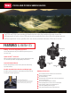
SPECIFICATIONS
Operational
• Flow Range:
– 1” – 5 to 40 gpm
– 1½” – 30 to 110 gpm
– 2” – 80 to 180 gpm
• Operating Pressure (220 psi maximum pressure rating):
– 1” – 1½” – 10 to 220 psi
– 2” – 20 to 220 psi
• EZReg
®
Pressure regulating:
– Outlet: 5 to 100 psi ± 3 psi
• Inlet: 10 to 220 psi
• Minimum pressure differential (between inlet and outlet)
for pressure regulation: 10 psi
• Burst pressure safety rating: 750 psi
• Body styles:
– Globe/Angle – 1”, 1½”, 2” female threads
• Spike Guard
™
Solenoid: 24 VAC (50/60 Hz) Standard
– Inrush: 60 Hz: 0.12 amps
– Holding: 60 Hz: 0.1 amps
• DC latching – momentary low voltage pulse
Dimensions
• 1” – 6
3
⁄4” H x 3
5
⁄8” W
• 1½” – 7¼” H x 3
5
⁄8” W
• 2” – 9½” H x 6
1
⁄8” W
Warranty
• Five years
Specifying Information—P220G and P220GS Series
P220GS -27-OX-XXX
Type Body Style Size Optional
P220GS 27 OX XXX
P220G—P220G Series Plastic Valve
P220GS—P220GS Plastic Scrubber Valve
27—NPT, Pressure-regulated (5–100 psi) 4—1"
6—1
1
/2"
8—2"
E—Effluent
DL—DC Latching Solenoid for GDC System
DLE—DC Latching Solenoid for GDC System, Effluent
Example: A 1” P220G Series plastic electric, pressure-regulating valve with a 60 Hz solenoid, would be specified as: P220G-27-04
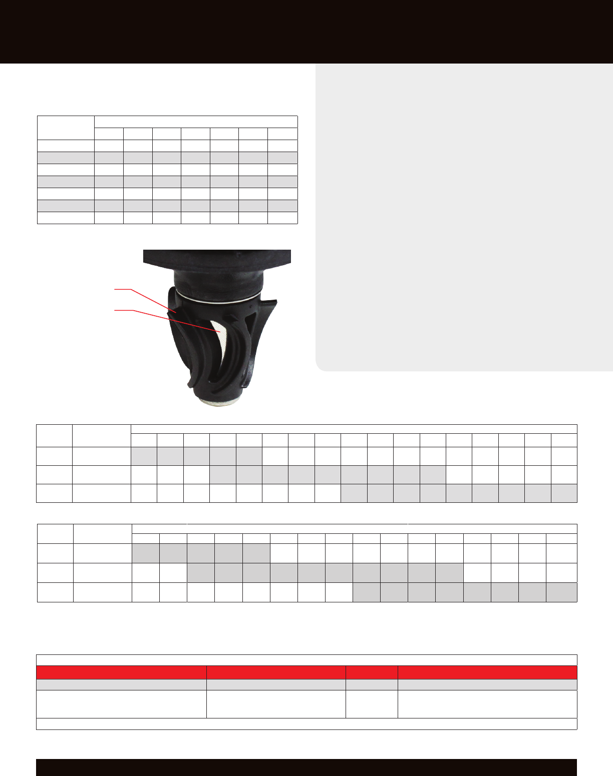
P220G SERIES FRICTION LOSS DATA*
Size Configuration
gpm Flow
5 10 20 30 40 50 60 70 80 90 100 110 120 130 140 150 180
1"
Globe
Angle
4.00
4.00
4.20
4.20
3.20
3.10
4.10
2.70
7.20
4.80
1
1
/2"
Globe
Angle
1.60
1.30
2.30
1.60
3.60
2.80
5.20
4.00
7.00
5.50
9.20
7.10
11.20
8.90
13.60
10.90
16.40
13.50
2"
Globe
Angle
2.10
1.20
2.70
1.60
3.30
2.00
4.00
2.40
4.80
2.80
5.60
3.30
6.50
3.90
7.50
4.40
8.70
5.20
P220GS SERIES FRICTION LOSS DATA*
Size Configuration
gpm Flow
5 10 20 30 40 50 60 70 80 90 100 110 120 130 140 150
1"
Globe
Angle
4.63
4.14
4.74
4.64
3.10
2.54
6.05
5.53
10.75
9.46
1
1
/2"
Globe
Angle
1.14
0.95
1.56
1.51
2.85
2.28
4.36
3.69
6.28
5.29
8.57
6.97
11.20
9.26
14.03
11.80
17.20
14.60
20.46
17.40
2"
Globe
Angle
3.57
2.79
4.62
3.50
5.33
4.41
6.80
5.62
8.20
6.39
9.02
7.35
10.46
8.81
11.61
9.37
Note: For optimum performance when designing a system, be sure to calculate total friction loss to ensure sufficient downstream pressure.
For optimum regulation performance, size regulating valves toward the higher flow ranges.
Flow rates are recommended not to exceed 5 psi loss.
VALVE WIRE SIZING CHART
Maximum One-way Distance (in ft.) Between Controller
and Valve Using Spike-Guard
™
Solenoid*
Ground Wire
Control Wire
18 16 14 12 10 8 6
18 2040 2520 2940 3280 3540 3720 3860
16 2520 3260 4000 4660 5220 5620 5920
14 2940 4000 5180 6360 7420 8300 8960
12 3280 4660 6360 8240 10100 11800 13180
10 3540 5220 7420 10100 13180 16060 18770
8 3720 5260 8300 11800 16060 20800 25540
6 3860 5960 8960 13180 18700 25540 33080
* Solenoid Model: 24 V ac
Pressure: 150 psi
Voltage Drop: 4 V
Minimum Operating Voltage: 20 V
Amperage (peak) 0.12 A
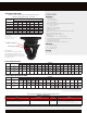
ACT
™
System
Toro’s patented technology employs a
constantly rotating turbine to clean the
metering/filtration area. This ensures that
dirt, algae and particulates do not impede
valve performance.
Filter Surface
“Scrubber” Turbine
www.toro.com / The Toro Company, Irrigaon Division / 5825 Jasmine Street, Riverside, CA 92504 / 877-345-8676 / Specicaons subject to change without noce / © 2016. All rights reserved / P/N 16-5015-IG