
Manual


Field Wire Installation
CAUTION: The OSMAC Satellite is capable of operating up to 31 stations simultaneously when operating with a
pump, or 32 stations simultaneously without a pump. To prevent possible satellite damage, total output current load
must not exceed 3.0 amps. If more than one valve per station will be connected, calculate the total in-rush current load
which would be imposed in the maximum operating conditions and use this value as a guide during installation and
operation of the satellite.
Procedure
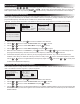
Multiple Controllers
Single Controller
Pressure Switch With
Controller Override
Starter
Power
Source
Starter
Power
Source
Starter
Power
Source
Pump Power
Source
Pressure Switch
Pump Power
Source
Pump Power
Source
Relay
24 V a.c.
1A Max.
Relay
24 V a.c.
1A Max.
(Typical)
Relay
24 V a.c.
1A Max.
Pump
Pump
Pump
Pump
Pump
Pump
Pump
Com
Com
Com
Com
Magnetic
Pump
Starter
Magnetic
Pump
Starter
Mag.
Pump
Starter
To Other
Controllers
Figure 5
Figure 6
3A Fuse
Pump Switch
Common Switch
Output Switch
Field Common
Terminals
Pump Terminal
Stations 1–32
Output Terminals
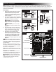
1. Attach the control and common wires
to each valve and/or valve-in-head
solenoid leads using an approved
waterproof splicing method. Route the
wires into the satellite through the 3"
(76mm) conduit.
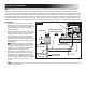
2. If an automatic pump start is required,
refer to the applicable wiring diagram in
Figure 5 and install accordingly.
CAUTION: Do not connect the
pump starter directly to the satellite’s
pump start circuit – damage to the
satellite will result.
Note: The pump circuit can also
be utilized to control a master valve if
required.
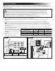
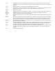
3. Secure the eld common wire(s) and
pump start relay (or master valve) wire
to the appropriate terminals on the
Pump/Com module. See Figure 6.
4. Secure the valve control wires to
the station terminals in the preferred
order of operating sequence. Station
terminals are numbered left to right,
1–32 (front) and 33–64 (back). Each
terminal can accommodate two 14
gage (1.5mm
2
) solid copper wires. See
Figure 6.
Note: The 3-position toggle switches
provided on the Relay Boards enable local
control of the eld common, pump circuit
and station outputs. The switch positions
are as follows:
ON (up) – Manually activates the circuit.
The pump, eld common or station output
will remain on until the switch is moved to
the AUTO or OFF position.
OFF (center) – Manually opens the circuit.
Operation of the circuit will not occur while
the switch is in this position.
AUTO (down) – Enables the circuit to be
automatically controlled during automatic
or manual (hand-held radio) operation.
CAUTION: To prevent damage to the
station output circuit fuse, do not exceed
3 Amp load when manually activating
multiple station outputs.