
User Manual

HMC5883
8 www.honeywell.com
BASIC DEVICE OPERATION
Anisotropic Magneto-Resistive Sensors
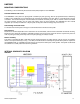
The Honeywell HMC5883 magnetoresistive sensor circuit is a trio of sensors and application specific support circuits to
measure magnetic fields. With power supply applied, the sensor converts any incident magnetic field in the sensitive axis
directions to a differential voltage output. The magnetoresistive sensors are made of a nickel-iron (Permalloy) thin-film and
patterned as a resistive strip element. In the presence of a magnetic field, a change in the bridge resistive elements
causes a corresponding change in voltage across the bridge outputs.
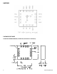
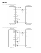
These resistive elements are aligned together to have a common sensitive axis (indicated by arrows on the pinouts) that
will provide positive voltage change with magnetic fields increasing in the sensitive direction. Because the output only is in
proportion to the one-dimensional axis (the principle of anisotropy) and its magnitude, additional sensor bridges placed at
orthogonal directions permit accurate measurement of arbitrary field direction.
Self Test
To check the HMC5883 for proper operation, a self test feature in incorporated in which the sensor is internally excited
with a nominal magnetic field (in either positive or negative bias configuration). This field is then measured and reported.
See SELF TEST OPERATION section below.
Power Management
This device is capable of operating with a single supply (AVDD) or dual supplies (AVDD and DVDD). Pin VREN makes
this selection by enabling the internal digital supply voltage regulator. When VREN is tied to AVDD, the device is in single
supply operation; this device is powered from AVDD; and the internal voltage regulator is enabled. When VREN is tied
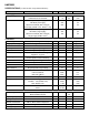
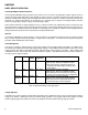
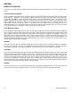
to AGND this devices operates with both AVDD and DVDD as supplies. The table below shows the modes available at
the various power supply conditions.
Table 2: Operational Modes and Supply States
Voltage Regulator
This ASIC has an internal voltage regulator which, depending on the application needs, may be used instead of supplying
voltage to pin DVDD. If DVDD pin is used, the internal voltage regulator is not engaged. When both supplies are used,
DVDD is typically high before AVDD, but no latch-up conditions will exist if DVDD is brought high after AVDD.
DVDD
AVDD
Pin
VREN
Modes
Supported
Description
High
High
AGND
All
Internal voltage regulator: Disabled.
Digital I/O pins: Range from DGND to DVDD.
Device fully functional. Digital logic blocks are
powered from DVDD supply, including all on-
board clocks.
High
Low
AGND
Idle, Sleep
Internal voltage regulator: Disabled.
Digital I/O pins: Range from DGND to DVDD.
Device Measurement functionality not supported.
Device I
2
C bus and register access supported.
Internally
regulated
High
AVDD
All
Internal voltage regulator: Enabled
Digital I/O pins: Range from AGND to AVDD
Device fully functional. Digital logic blocks are
powered through on-board regulator.