
User Manual

HMC5883
www.honeywell.com 3
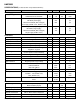
Absolute Maximum Ratings (* Tested at 25°C except stated otherwise.)
Characteristics
Min
Max
Units
Supply Voltage AVDD
-0.3
5
Volts
Supply Voltage DVDD
-0.3
2
Volts
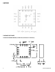
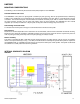
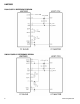
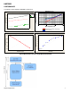
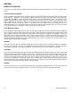
PIN CONFIGURATIONS
(Arrow indicates direction of applied field that generates a positive output voltage after a SET pulse.)
Pin
Name
Description
1
SCL
Serial Clock – I2C Master/Slave Clock
2
AVDD
Analog Positive Supply
3
NC
Not to be Connected
4
NC
No Connection
5
NC
No Connection
6
NC
No Connection
7
NC
No Connection
8
SETP
Set/Reset Strap Positive – S/R Capacitor (C2) Connection
9
GND
Supply Ground/Return
10
C1
Reservoir Capacitor (C1) Connection
11
GND
Supply Ground/Return
12
SETC
S/R Capacitor (C2) Connection
13
DVDD
Digital Positive Supply
14
VREN
Voltage Regulator Enable, (GND = Dual Supply, AVDD = Single Supply)
15
DRDY
Data Ready, Interrupt Pin. Nominally high. Low for 5usec when data is
placed in the output registers
16
SDA
Serial Data – I2C Master/Slave Data
Table 1: Pin Configurations