
User Manual

HMC5883
16 www.honeywell.com
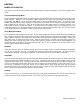
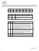
DZRA7
DZRA6
DZRA5
DZRA4
DZRA3
DZRA2
DZRA1
DZRA0
(0)
(0)
(0)
(0)
(0)
(0)
(0)
(0)
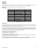
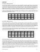
DZRB7
DZRB6
DZRB5
DZRB4
DZRB3
DZRB2
DZRB1
DZRB0
(0)
(0)
(0)
(0)
(0)
(0)
(0)
(0)
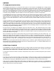
Table 19: Data Output Z Registers A and B
Data Output Register Operation
When one or more of the output registers are read, new data cannot be placed in any of the output data registers until all
six data output registers are read. This requirement also impacts DRDY and RDY, which cannot be cleared until new
data is placed in all the output registers.
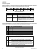
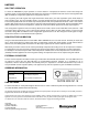
Status Register
The status register is an 8-bit read-only register. This register is used to indicate device status. SR0 through SR7
indicate bit locations, with SR denoting the bits that are in the status register. SR7 denotes the first bit of the data stream.
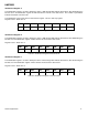
SR7
SR6
SR5
SR4
SR3
SR2
SR1
SR0
(0)
(0)
(0)
(0)
(0)
REN (0)
LOCK (0)
RDY(0)
Table 20: Status Register
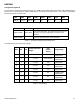
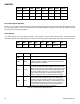
Location
Name
Description
SR7 to
SR3
0
These bits must be cleared for correct operation.
SR2
REN
Regulator Enabled Bit. This bit is set when the internal
voltage regulator is enabled. This bit is cleared when the
internal regulator is disabled.
SR1
LOCK
Data output register lock. This bit is set when this some but
not all for of the six data output registers have been read.
When this bit is set, the six data output registers are locked
and any new data will not be placed in these register until
on of four conditions are met: one, all six have been read
or the mode changed, two, a POR is issued, three, the
mode is changed, or four, the measurement is changed.
SR0
RDY
Ready Bit. Set when data is written to all six data registers.
Cleared when device initiates a write to the data output
registers, when in off mode, and after one or more of the
data output registers are written to. When RDY bit is clear
it shall remain cleared for a minimum of 5 μs. DRDY pin
can be used as an alternative to the status register for
monitoring the device for measurement data.
Table 21: Status Register Bit Designations