
User Manual

HMC5883
14 www.honeywell.com
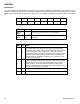
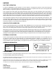
Mode Register
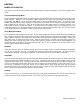
The mode register is an 8-bit register from which data can be read or to which data can be written. This register is used to
select the operating mode of the device. MR0 through MR7 indicate bit locations, with MR denoting the bits that are in the
mode register. MR7 denotes the first bit of the data stream. The number in parenthesis indicates the default value of that
bit.
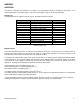
MR7
MR6
MR5
MR4
MR3
MR2
MR1
MR0
(0)
(0)
(0)
(0)
(0)
(0)
MD1 (0)
MD0 (1)
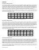
Table 14: Mode Register
Location
Name
Description
MR7 to
MR2
0
These bits must be cleared for correct operation.
MR1 to
MR0
MD1 to
MD0
Mode Select Bits. These bits select the operation mode of
this device.
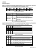
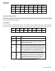
Table 15: Mode Register Bit Designations
MD1
MD0
Mode
0
0
Continuous-Measurement Mode. In continuous-measurement mode,
the device continuously performs measurements and places the
result in the data register. RDY goes high when new data is placed
in all three registers. After a power-on or a write to the mode or
configuration register, the first measurement set is available from all
three data output registers after a period of 2/f
DO
and subsequent
measurements are available at a frequency of f
DO
, where f
DO
is the
frequency of data output.
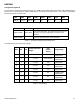
0
1
Single-Measurement Mode (default). When single-measurement
mode is selected, device performs a single measurement, sets RDY
high and returned to sleep mode. Mode register returns to sleep
mode bit values. The measurement remains in the data output
register and RDY remains high until the data output register is read
or another measurement is performed.
1
0
Idle Mode. Device is placed in idle mode.
1
1
Sleep Mode. Device is placed in sleep mode.
Table 16: Operating Modes