
User Manual

HMC5883
www.honeywell.com 13
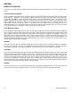
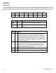
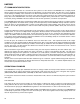
Configuration Register B
The configuration register B for setting the device gain. CRB0 through CRB7 indicate bit locations, with CRB denoting the
bits that are in the configuration register. CRB7 denotes the first bit of the data stream. The number in parenthesis
indicates the default value of that bit.
CRB7
CRB6
CRB5
CRB4
CRB3
CRB2
CRB1
CRB0
GN2 (0)
GN1 (0)
GN0 (1)
(0)
(0)
(0)
(0)
(0)
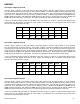
Table 10: Configuration B Register
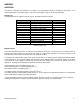
Location
Name
Description
CRB7 to CRB5
GN2 to GN0
Gain Configuration Bits. These bits configure the gain for
the device. The gain configuration is common for all
channels.
CRB4 to CRB0
0
This bit must be cleared for correct operation.
Table 11: Configuration Register B Bit Designations
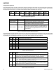
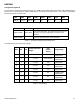
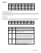
The table below shows nominal gain settings.
GN2
GN1
GN0
Sensor Input Field
Range:
Gain
(counts/
Gauss)
Output Range
0
0
0
± 0.9 Ga
1280
0xF800–0x07FF
(-2048–2047 )
0
0
1
± 1.2 Ga
1024 (default)
0xF800–0x07FF
(-2048–2047 )
0
1
0
± 1.9 Ga
768
0xF800–0x07FF
(-2048–2047 )
0
1
1
± 2.5 Ga
614
0xF800–0x07FF
(-2048–2047 )
1
0
0
± 4.0 Ga
415
0xF800–0x07FF
(-2048–2047 )
1
0
1
± 4.6 Ga
361
0xF800–0x07FF
(-2048–2047 )
1
1
0
± 5.5 Ga
307
0xF800–0x07FF
(-2048–2047 )
1
1
1
± 7.9 Ga
219
0xF800–0x07FF
(-2048–2047 )
Table 12: Gain Settings