
User Manual

Data sheet
BMP085
Page 18
BST-BMP085-DS000-06 | Revision 1.3 | August 2011 Bosch Sensortec
© Bosch Sensortec GmbH reserves all rights even in the event of industrial property rights. We reserve all rights of disposal such as copying and passing on to
third parties. BOSCH and the symbol are registered trademarks of Robert Bosch GmbH, Germany.
Note: Specifications within this document are subject to change without notice.
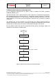
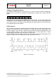
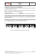
4.4 Start temperature and pressure measurement
The timing diagrams to start the measurement of the temperature value UT and pressure value
UP are shown below. After start condition the master sends the device address write, the
register address and the control register data. The BMP085 sends an acknowledgement
(ACKS) every 8 data bits when data is received. The master sends a stop condition after the
last ACKS.
ACKS
S
ACKS
Module address
write 0xEE
Register address
0xF4
Control register
data
0
xF4
SCL
SDA
ACKS P
Figure 6: Timing diagram for starting pressure measurement
Abbreviations:
S Start
P Stop
ACKS Acknowledge by Slave
ACKM Acknowledge by Master
NACKM Not Acknowledge by Master
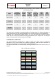
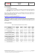
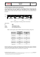
Table 6: Control registers values for different internal oversampling_setting (osrs)
Measurement
Control register
value
(register address
0xF4)
Max. conversion
time
[ms]
Temperature 0x2E 4.5
Pressure
(osrs = 0)
0x34 4.5
Pressure
(osrs = 1)
0x74 7.5
Pressure
(osrs = 2)
0xB4 13.5
Pressure
(osrs = 3)
0xF4 25.5
Instead
of waiting for the maximum conversion time, the output pin EOC (end of conversion)
can be used to check if the conversion is finished (logic 1) or still running (logic 0). After the
conversion is finished BMP085 switches automatically in standby mode.