
User Manual

Data sheet
BMP085
Page 17
BST-BMP085-DS000-06 | Revision 1.3 | August 2011 Bosch Sensortec
© Bosch Sensortec GmbH reserves all rights even in the event of industrial property rights. We reserve all rights of disposal such as copying and passing on to
third parties. BOSCH and the symbol are registered trademarks of Robert Bosch GmbH, Germany.
Note: Specifications within this document are subject to change without notice.
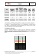
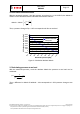
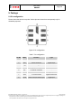
4.2 Device and register address
The BMP085 module address is shown below. The LSB of the device address distinguishes
between read (1) and write (0) operation, corresponding to address 0xEF (read) and 0xEE
(write).
A7 A6 A5 A4 A3 A2 A1 W/R
1 1 1 0 1 1 1 0/1
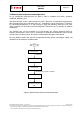
There is an easy way to connect two BMP085 to the same I
2
C bus: You can use the XCLR input
of BMP085 to set one BMP085 part silent while you communicate with the other BMP085 part
via I
2
C and vice versa. The signals can be provided by two digital outputs of the microcontroller,
or one digital output and one inverter.
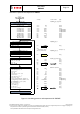
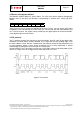
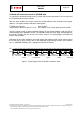
4.3 I²C protocol
The I
2
C interface protocol has special bus signal conditions. Start (S), stop (P) and binary data
conditions are shown below. At start condition, SCL is high and SDA has a falling edge. Then
the slave address is sent. After the 7 address bits, the direction control bit R/W selects the read
or write operation. When a slave device recognizes that it is being addressed, it should
acknowledge by pulling SDA low in the ninth SCL (ACK) cycle.
At stop condition, SCL is also high, but SDA has a rising edge. Data must be held stable at SDA
when SCL is high. Data can change value at SDA only when SCL is low.
Figure 5: I²C protocol