
User Manual

Data sheet
BMP085
Page 16
BST-BMP085-DS000-06 | Revision 1.3 | August 2011 Bosch Sensortec
© Bosch Sensortec GmbH reserves all rights even in the event of industrial property rights. We reserve all rights of disposal such as copying and passing on to
third parties. BOSCH and the symbol are registered trademarks of Robert Bosch GmbH, Germany.
Note: Specifications within this document are subject to change without notice.
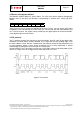
4. I²C Interface
• I²C is a digital two wire interface
• Clock frequencies up to 3.4mBit/sec (I²C standard, fast and high-speed mode supported)
• SCL and SDA needs a pull-up resistor, typ. 4.7 kOhm to V
DDD
(one resistor each for all
the I²C bus)
The I
2
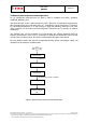
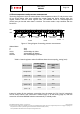
C bus is used to control the sensor, to read calibration data from the E
2
PROM and to
read the measurement data when A/D conversion is finished. SDA (serial data) and SCL
(serial clock) have open-drain outputs.
For detailed I
2
C-bus specification please refer to:
http://www.nxp.com/acrobat_download/literature/9398/39340011.pdf
The BMP085 has a master clear (XCLR) low-active input that is used to reset the BMP085 and
initializes internal registers and counters. The device is automatically reset by power on reset
(POR) circuitry. XCLR can be left floating if not used. The pad has an internal pull-up resistor of
typ. 120kOhm.
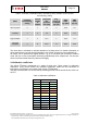
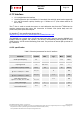
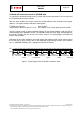
4.1 I²C specification
Table 5: Electrical parameters for the I
2
C interface
Parameter Symbol Min. Typ Max. Units
Clock input frequency f
SCL
3.4 MHz
Input-low level V
IL
0 0.2 * V
DDD
V
Input-high level V
IH
0.8 * V
DDD
V
DDD
V
SDA and SCL pull-up resistor R
pull-up
2.2 10 kOhm
SDA sink current
@ V
DDD
= 1.62V, V
OL
= 0.3V
I
SDA_sink
9 mA
EOC sink current
@ V
DDD
= 1.62V, V
OL
= 0.3V
I
SDA_sink
7.7 mA
EOC source current
@ V
DDD
= 1.62V, V
OH
= 1.32V
I
SDA_source
1.5 mA
XCLR pulse length t
XCLR
1 μs
Start-up time after power-up, before
first communication
t
Start
10 ms