
Manual

3
As a best practice, Toro recommends that all ground and
surge devices be checked annually and/or after a signicant
lightning event.
All other electrical equipment grounds must meet local
electrical codes.
Toro advises against the use of a bonding/shielding wire to
protect the Toro components of Toro control systems.
Grounding materials or equipment that is not specied in the
Toro installation instructions must not be connected to the
Toro communication/power wiring or the grounding for the
communication/power wiring.
Fuse Devices
Fuse devices, like the Paige DCFD, work like isolation valves
for the communication wiring. We allow using these devices
(or equivalent) at signicant cable junction points in order
to facilitate isolation and troubleshooting without having
to disconnect wires or waterproof splices. If DCFD devices
are used, we recommend a 20-amp fuse, not a 5-amp fuse.
In high lightning areas, we recommend the addition of one
DEC-SG-LINE surge device on the input and all outputs of
the DCFD and that they should be grounded per grounding
recommendations listed above.
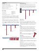
High Voltage Cables
Toro recommends that all communication cables be kept
separate from mains power cabling. Power cables which
have a higher voltage than communication/mains control
cabling will induce a voltage into that communication line
through transformer eect. is will be detrimental to the
communication reliability. All cables must be separated from
high voltage power lines by at least 30cm per these guidelines
Power Cable Circuit Rating
(max KVA*)
Recommended Minimum
Spacing**
0-5 KVA 30cm
5-10 KVA 60cm
10-20 KVA 120cm
>20 KVA 3m
* Maximum Voltage x Current ratings of circuit
** ese are minimum spacing recommendations to minimize
noise coupling. ere may be greater separation required by
safety agencies of local codes.
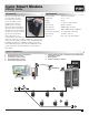
The Components
Software
Lynx V7.0 or later
FIU
e FIU is used in all systems. It provides
the communication link between
the PC and the Lynx Smart Hub(s).
Communication can be by wireline or radio.
FIU-2010 wireline only
communication
FIU-2011DR wireline and radio
communication
Lynx Smart Hub
e Lynx Smart Hub is the interface that
converts the signals from the computer
into the 2-way high speed data signal
that goes out to all of the Lynx Smart
Modules. All systems require at least one
Hub. It can be installed in the oce, next
to the computer, or in a remote location
on the golf course.
Features
• Plastic pedestal or metal wall-mount
enclosure
• Local or Remote Mounting
• Wired or Radio Communication –
up to two miles
• Faceplate stores a downloaded
irrigation program, shows what is
running, and allows manual
watering.
Each of the Lynx Smart Hubs (up
to 20 per system), can have wire or
radio communication. If you have
two or more Lynx Smart Hubs
co-located, and you are using radio
communication, you only need
one unit with radio and the other
co-located Lynx Smart Hubs can
communicate with the radio Lynx
Smart Hub via wire.
Front Panel Controls
• e Lynx Smart Hub receives a list of up to 1000 stations
that will run automatically, even if communication is
interrupted
• Program list can be viewed under scheduled activity
• Features multi-manual program, with up to 500 stations
and 50 simultaneous stations
• All currently running stations can be stopped at once
• Communication can be monitored between the Lynx
Smart Hub and the central FIU.
FIU
ON
1 2 3 4
ON
1 2 3 4
pedestal
– +
HOME
%ADJUST START PAUSE/
RESUME
STOP SYSTEM
SETTINGS
MANUAL
WATERING
SCHEDULED
WATERING
DIAGNOSTICS STATION
SETTINGS
wall-mount