
Manual

2
Capacity
Lynx Smart Hubs per system 20
Modules per Lynx Smart Hub 1000
Daughter boards per Lynx Smart Hub 2
Wire paths per daughter board 2
Modules per wire path 250
Simultaneous solenoids per wire path 50
Wire Sizing
Sleep current 0.00014 amps
Active current 0.00070 amps
Average current 0.00025 amps
Maximum design voltage drop 3.0 volts
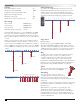
Total main cable length not to exceed 15,000 feet (14 AWG).
Total spur cable amount is unlimited, as long as the furthest
module is not further than 15,000 feet from the Lynx Smart
Hub. A cable should never form a loop that is connected back
to itself.
If there is a long section of cable with no modules attached,
that length should be counted as double, or increase the size
of that section from 14 AWG up to 12 AWG. For example, if
there is a 5000 ft section with no modules, count it as 10,000
ft or use 5000 ft of 12 AWG for the section with no modules.
Station Numbering
To optimize the advanced diagnostic features, the station
numbering should follow the wire, with the lowest station
numbers closest to the Lynx Smart Hub and the highest
station numbers at the end of the main cable path. Branches
should be included in the numbering sequence as shown.
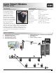
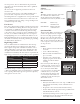
Surge Device
DEC-SG-LINE
Spacing of surge devices is 1000 ft (305m). Each LSM
should be within 500ft (150m) of a surge device. Connect
white wire to white communication wire, black wire to black
communication wire, green wire to ground. Long sections of
cable without LSM modules do not require surge devices.
Wire
14 AWG, two-conductor, insulated wire suitable for direct
burial applications for operation up to 600 volts and
conductor temperatures up to 60°C. Listed by UL, ETL
or CSA. Soft drawn bare copper conductor meeting the
requirements of ASTM specication B-3 or B-8. PE or PVC
insulation, 1 or two layers, minimum thickness .075 inches.
Paige P7389D, Paige P7350D, P7072D, or equivalent.
Splices
All splices should be made with either Toro Golf
Red connector 363-6443 or 3M DBR/Y-6
Grounding
Toro surge protection devices require an
acceptable ground to dissipate excess energy.
In all cases a ground is required and the lower the
resistance the more eectively those surge protection devices
will operate.
Grounding for surge protection must be measured at the time
of installation and Toro recommends a resistance reading of
10 ohms or less.
e installation of a ground rod, a ground plate, and
enhancement material at each ground device should be
used as a best practice. When these devices are installed per
the manufacturer’s instructions, this grounding strategy is
considered eective; yet may not always achieve the 10-ohm
or less recommendation.
11,250’
7500’
3750’
3750’3750’3750’
main cable
spur cable
5000’ main cable without modules,
should be counted as 10,000’ or
increase to 12 AWG
5000’ main cable with modules
spur cable
spur cable
3750’
1
2
3
4
5
6
7
8
15
16
23
24
17
18
19
9
10
11
12
13
14
20
21
22
25
26
27
The Details