
Manual

Grounding a Controller
Installation Guide
Grounding a Controller
Installation Guide
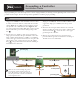
A
B
C
SIDE
Make sure the soil surrounding the ground
rod and plate remains well moistened at all
times. e addition of some form of irrigation
may be required if the controller is installed in
a non-irrigated location.
grounding rod
no sharp bends
valve box
grounding lug
grounding plate
30” (80 cm) trench
12” (30 cm) trench12” (30 cm) trench
1. Drive a 5/8” by 8’ (17mm x 2.5m) copper clad steel rod
(Paige part # 182000) into well moistened soil not less than
8’ (2.5m) or not more than 12’ (3.7m) from the controller
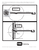
cabinet (Figure 1). For 2-Wire systems, install the ground
rod adjacent to the communication cable (Figure 2). e
top of the ground rod should be ush with or below ground
level, and should be protected from damage using a valve
box (
A
).
2. Install a 4” by 96” (10cm x 2.5m) copper ground plate
(Paige part # 182199IC). e plate should be at least .06”
thick (1.5mm) and should have a 6 AWG x 12’ (10mm²
x 4m) solid copper, insulated wire welded to the plate. e
plate should go into a trench that is at least 30” (80cm)
deep (
B
). Use ground enhancement material (GEM) per
the manufacturer’s directions.
3. Using a 5/8” (17mm) clamp or exothermic-weld fastener
(Paige part # 1820039P), attach an 8 AWG (10mm²) solid
copper wire (Paige part # 160629) near the top of the
ground rod.
4. Route the wire through conduit and into the controller
cabinet, avoiding wire bends of less than 8” (20cm) radius
and more than 90° (
C
). Secure the wire to the copper
ground lug in the controller.
5. Measure the ground resistance per the instructions
provided with the ground test instrument. A reading of
10 ohms or less is recommended.
Steps
Proper grounding of a controller is important to ensure a high probability of surviving a nearby lightning strike as well as other
possible electrical surges. Toro has developed these guidelines to facilitate proper grounding.