
Data Sheet

3
MachXO2 Breakout Board
Evaluation Kit User’s Guide
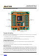
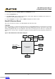
Figure 1. MachXO2 Breakout Board, Top Side
Two 2x20
Header Landings
(J3, J5)
Two 2x20
Header Landings
(J2, J4)
MachXO2
PLD (U3)
FTDI
USB to UART/FIFO
IC (U1)
JTAG Header
Landing (J1)
USB Mini-B
Socket (J7)
Power LED
(PWR_ON)
Power/GND
Test Points
(TP1, TP2, TP3)
4x15 60-Hole
Prototype Array (J6)LED Array (J4)
Storage and Handling
Static electricity can shorten the lifespan of electronic components. Please observe these tips to prevent damage
that could occur from electro-static discharge:
• Use anti-static precautions such as operating on an an
ti-static mat and wearing an anti-static wrist-band.
• Store the evaluation board in the packaging provided.
• Touch a metal USB housing to equalize voltage potential between you and the board.
Software Requirements
You should install the following software before you begin developing new designs for the Breakout board:
• Lattice Diamond
®
design software
• FTDI Chip USB hardware drivers (installed as an option within the Diamond installation program)
MachXO2 Device
This board currently features the MachXO2-7000HE FPGA which offers embedded Flash technology for instant-
on, non-volatile operation in a single chip. Numerous system functions are included, such as two PLLs and 256
Kbits of embedded RAM plus hardened implementations of I
2
C, SPI, timer/counter, and user Flash memory. Flexi-
ble, high performance I/Os support numerous single-ended
and differential standards including LVDS, and also
source synchronous interfaces to DDR/DDR2/LPDDR DRAM memory. The 144-pin TQFP package provides up to
Downloaded from Arrow.com.Downloaded from Arrow.com.Downloaded from Arrow.com.