
Data Sheet

14
MachXO2 Breakout Board
Evaluation Kit User’s Guide
Table 9. JTAG Programming Pin Information
Description MachXO2 Pin
Test Data Output 137:TDO
Test Data Input 136:TDI
Test Mode Select 130:TMS
Test Clock 131:TCK
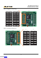
LEDs
A green LED (D9) is used to indicate USB 5V power. Eight red LEDs are driven by I/O pins of the MachXO2 device.
Table 10. Power and User LEDs Reference
Item Description
Reference Designators
Red LEDs (D1, D2, D3, D4, D5, D6, D7, D8)
Green LEDs (D9)
Part Number
LTST-C190KRKT (D1-D8)
LTST-C190KGKT (D9)
Manufacturer Lite-On It Corporation
Web Site www.liteonit.com
Power Supply
3.3V and 1.2V power supply rails are converted from the USB 5V interface when the board is connected to a host
PC
.
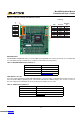
Test Points
In order to check the various voltage levels used, test points are provided:
•TP1: +3.3V
•T
P2: +1.2V
• TP3: GND
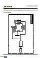
USB Programming and Debug Interface
The USB mini-B socket of the Breakout Board serves as the programming and debug interface.
JTAG Programming: For JTAG programming, a preprogrammed USB PHY peripheral controller is provided on the
Breakout Board to serve as the programming interface to the MachXO2 FPGA.
Programming requires the Lattice Diamond or ispVM System software.
Table 11. USB Interface Reference
Item Description
Reference Designators U1
Part Number FT2232HL
Manufacturer Future Technology Devices International (FTDI)
We
b Site www.ftdichip.com
Downloaded from Arrow.com.Downloaded from Arrow.com.Downloaded from Arrow.com.Downloaded from Arrow.com.Downloaded from Arrow.com.Downloaded from Arrow.com.Downloaded from Arrow.com.Downloaded from Arrow.com.Downloaded from Arrow.com.Downloaded from Arrow.com.Downloaded from Arrow.com.Downloaded from Arrow.com.Downloaded from Arrow.com.Downloaded from Arrow.com.