
User Manual

LCD12864-COG
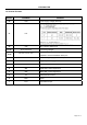
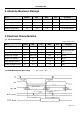
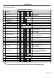
4.5 Display Commands
Code
No.
Instrctions
A0
/RD
/WR
D7
D6
D5
D4
D3
D2
D1
D0
Function
1
Display ON/OFF
0 1 0 1 0 1 0 1 1 1
DON
DON=0,display off
DON=1,display on
2
Display start line set
0 1 0 0 1
Display start address
Set the display RAM display start line address
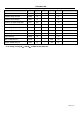
3
Set Page Address
0 1 0 1 0 1 1
Page address
Set the display RAM Page address
Ser Column Address
(Upper-4 bits)
0 1 0 0 0 0 1 Col. Add Set the upper-4-bit of column address counter
4
Ser Column Address
(Lower-4 bits)
0 1 0 0 0 0 0 Col. Add Set the low-4-bit of column address counter
5
Read Staus
0 0 1 Status 0 0 0 0 Read the status data
6
Write Display Data
1 1 0 Write Data Write data into the display RAM
7
Read Display Data
1 0 1 Read Data Read data from the display RAM
8
ADC Select
0 1 0 1 0 1 0 0 0 0
ADC
Set the display RAM address SEG output
Correspondence
ADC = 0,Normal. ADC = 1,Reverse
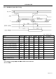
9
Normal/Reverse Display
0 1 0 1 0 1 0 0 1 1
REV
REV = 0, Normal
REV = 1, Reverse
10
Entire Display ON/OFF
0 1 0 1 0 1 0 0 1 0
EON
EON = 0, Normal
EON = 1, Entire display ON
11
Set LCD Bias
0 1 0 1 0 1 0 0 0 1
BIAS
Bias = 0, 1/9 Bias
Bias = 1, 1/7 Bias
12
Set Read-Modify-Write
0 1 0 1 1 1 0 0 0 0 0 Enter the “Read-Modify-Write” mode
13
Reset Read-Modify-Write
0 1 0 1 1 1 0 1 1 1 0 Clear the “Read-Modify-Write” mode
14
Reset
0 1 0 1 1 1 0 0 0 1 0 Resets the LCD module
15
SHL S elect 0 1 0 1 1 0 0
SHL
***
Set the COM scanning direction
SHL = 0, Normal
SHL = 1, Flipped in y-direction
* = don’t care terms
16
Power Control Set 0 1 0 0 0 1 0 1
VC
VR
VF
Set the power circuit operation mode
VF : LCD Supply Voltage Follower
VR : LCD Supply Voltage Regulator
VF : LCD Supply Voltage Converter
(1 = ON, 0 = OFF)
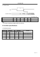
17
Regulator Resistor Select 0 1 0 0 0 1 0 0 Ratio Set the built-in resistor ratio (Rb/Ra)
Electronic volume mode set 0 1 0 1 0 0 0 0 0 0 1 Set reference voltage mode
18
Electronic volume register set
0 1 0 * *
Electronic
Control value
Set reference voltage register
19
Power Save
- - - -------
Compound instruction
Display OFF + Entire Display ON
20
NOP 0 1 0 1 1 1 0 0 0 1 1 Non-operation command
Note:
*a. For the details of the Display Commands, please refer to ST7565R data sheet
Page 10 of 14