
User Manual

Visit our Page LaisDcc
TM
Decoders Manual Sales@laisdcc.com
www.laisdcc.com 2002-2018 ©LaisDcc
TM
17 / 17
Now... Let’s do it as a step-by-step setup - we will use the White and yellow function wires
for Rule 17.
(1) We need to set CV61 to engage “Opposite Dim”. Opposite dim needs 32 added to the
value already in CV61. As CV61 also controls BEMF it will already be either 1 (BEMF on) or 3
(BEMF on via a function button).
So... For CV 61, enter either 1+32 = 33 or 3+32 = 35.
(2) We need to set CV64 to set the Dimming level. The range for this CV is 0~15. We find the
best range to use to dim LEDS is 1~6. We use 3 with our own locomotives.
So... For CV 64, enter 3.
(3) Now we need to set White wire control / CV49 and Yellow wire control / CV50 to Rule 17
always on.
The options for this are 8 (Rule 17 fwd. only) 24 (rule 17 Rev only) or 40 (rule 17 always /
manual) So... For BOTH CV49 and CV50, enter 40.
(3) Now to reallocate function control. We are going to make White F0, Yellow F1, Green F2,
Purple F3. White is already F0 so leave it. To remap the others just set their function allocation
CVs to the following values.
CV34 enter 4, CV35 enter 8, CV36 enter 16.
Did you follow that OK? If so, then it is time to take a break & have a Play with Rule 17!
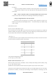
CV135: Random Flicker Adjust
For Random Flicker generator the overall speed of the flicker can be adjusted from 1-255 (1
being the fastest and 255 being the slowest).
LaisDCC decoder definition in JMRI can be find on our website or at the website of
https://github.com/JMRI/JMRI/blob/master/xml/decoders/LaisDcc.xml
Visit our website at www.laisdcc.com
We suggest you to buy our products via our whole sellers or distributors at your local country
so you can get a good after-sales service and fast reply.
If you want to be our whole sellers or distributor, please contact with us at Sales@laisdcc.com