
Full Product Manual
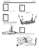
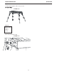
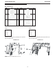
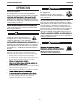
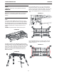
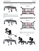
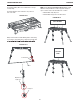
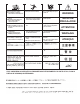
Table Of Contents

B-2
OPERATION
USERS
This product should only be used by authorized, trained and
MODIFICATIONS
manual, are not allowed. Modications will void the product
warranty.
PORTABLE WELDING TABLE
Modications of this product, other than those specied in this
OPERATION
To set up the Portable Welding Table, swing the legs open by
pressing the levers located on the inside of each leg and pulling
loaded locking buttons engage. Ensure that buttons fully extend
through the leg bracket hole, locking the legs into the open
position.
SETUP
the leg toward the back side of the leg bracket until the spring-
CAUTION: Keep hands and ngers away from pinch points.
FIGURE B.1
The height of the table can be adjusted by pressing the spring-
loaded push buttons on the legs in while sliding the lower section
with the positioning holes xing the leg length. Ensure that the
push-buttons are fully extended through the upper leg tube.
Attach the safety pins that are included with the table as an
additional precaution.
of the leg up or down. The spring-loaded push buttons will engage
FIGURE B.2
The Portable Welding Table has an earth ground bolt with two
nuts that is to be used to connect the table to electrical earth
sides of the table. Attach a copper lead from the earth ground
stud to earth or building frame per local and national electrical
codes.
ground. The stud can be mounted in the middle of any of the four
FIGURE B.3
The Portable Welding Table has tool holder features along the
edges of both sides of the table. Typical welding tools can be
stored for easy access.
FIGURE B.4