Garrden H Hose Reel R Cart C OWNER O R’S MANUA AL ITEM M# 59 9787 WAR RNING Read careffully and understand alll ASSEMBLY Y AND OPERATION INSSTRUCTION NS before opeerating. Failure to allow w the safetyy rules and other o basic safety precaution ns may result in seriouss personal injury.
INTENDED USE Heavy‐duty hose reel cart has a strong tubular steel frame, foam‐padded handle and tires for easy maneuverability. Holds up to 300 feet of garden hose for east reach to about anywhere in your yard. TECHNICAL SPECIFICATIONS Item Description 3—feet of 5/8 in hose (not included) 10 in. pneumatic Tubular powder‐coat steel frame Capacity Tires Construction GENERAL SAFETY RULES WARNING: Read and understand all instructions.
WORK AREA Keep work area clean, free of clutter and well lit. Cluttered and dark work areas can cause accidents. Keep children and bystanders away while operating a Hose Reel Cart and Hose. Distractions can cause you to lose control, so visitors should remain at a safe distance from the work area.
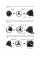
ASSEMBL A LY INSTR RUCTIONS 1.Place Fram me (A1) into o Frame (A22), and then n attach tw wo Support Brackets (K K) on both h side Fram me, and then n fasten witth two Boltts (6), Flat washers w (122) and Lock nuts (11)). Fig 1, Fig 2 Fig 1 Fig 2 u Slidde each Axle e (B) throug gh both endds of frame, 2. Sttand frame assembly upright. Mou unt the Wheels(C) into o the Axle (B B), and faste en with the Flat Washeer (10) and Lock L Nutt (9).
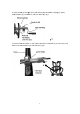
3. A Attach the Hose H reel (D D) to the onne side of th he Reel Roller (I); fasteen with six Bolts B (5). Fig 4 FFig 4 4. A Attach the Hose H reel (D) to the oother side of o the Reel Roller (I); ffasten with five Boltts (5) and please leavve the areaa that circle ed in Fig 5 unscrewedd for U braacket asseembly. Fig 5 Fig g5 5.
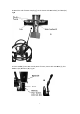
. C Crank handlee (E) througght the Crannk hub (H) in nto the Watter Couplingg (J), fasten with h two Bolts (3), Flat Waasher, and LLock Nuts (1 11). Fig 7 Fig g7 7. P Put the Hosee Reel Roller on the Fraame, Moun nt the Crankk Hub (L) to the Frame, and fasten with thee two Bolts (12) and Nuuts (11).
8. A Attach the end of Water Coupling ((J) to the Frrame with tw wo Bolts(1) and Nuts(1 11). Fig 9 Fig 9 9. Place Handlee (F) onto th he vertical pposts of Frame, Fasten with two BBolts (2), Flat Wasshers (12) and a Nuts (11 1).
10. Attach Baskket (H) to Handle (F) w ith two Boltts (4), Flat Washers W (8) and Hex Nuts (7). Fig 11 Figg 11 11. Place Rubber Washer (14) into th e female fittting of the Water Couppling (J), and attaach the Lead der Hose (G G) to the Waater Couplin ng (J).
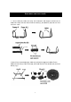
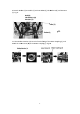
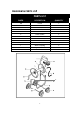
DIA AGRAM M & PAR RTS LISTT PA ARTS LIST PARTT# DEESCRIPTIO ON QUA ANTITY A1 1 A2 2 B C D E F G H I J K L Frame Frame Axles Wheels Hose Reel CCrank Handle Handle LLeader Hose Acccessories Baasket Roller W Water Coupliing Su pport Brackkets Crank Hub b 1 1 2 4 2 1 1 1 1 1 1 4 1 L 9
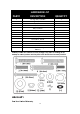
HARD DWAREE LIST PA ART# DESCRIPTIO ON QU UANTIT TY 2 Carriage Bolt, 6*35m mm 2 4 Carriage Bolt, 6*42m mm 3 2 Bolt,, 6*30mm 4 2 Bolt,, 8*45mm 5 13 Bolt,, 5*15mm 6 4 Bolt,, 6*45mm 7 2 Hex N Nut, 8mm 8 4 Flat waasher, 8mm m 9 4 Lock N Nut, 12mm 10 4 Flat waasher, 12mm m 11 12 Lock Nut, 6mm 12 12 Flat waasher, 6mm m 13 1 U Bracket 14 2 Rubberr Washer (Inncludes 1‐Sp pare Rubbe er W Washer) Careefully remo ove the conttents from the packagge.