FY-41AP Autopilot & OSD System Installation & Operation Manual Multi-rotor Version V2.22 And Above Guilin Feiyu Electronic Technology Co., Ltd Addr : 4th Floor,YuTaiJie Science Technology Building,Information Industry Park , ChaoYang Road ,Qi Xing District ,Gui Lin ,541004 Website: www.feiyu-tech.com Email: service@feiyu-tech.
Guilin Feiyu Electronic Technology Co., Ltd Table Of Content User Agreement ........................................................................................................................................ 1 1. FY-41AP Autopilot & OSD System Introduction .................................................................................. 2 2. Function Introduction .......................................................................................................................... 3 3.
Guilin Feiyu Electronic Technology Co., Ltd Dear Customer : Thank you for choosing FY-41AP as your autopilot system. Please read this manual carefully to ensure correct installation & operation. FY-41AP has both fixed wing and Multi-rotor versions. You can choose your preferred version while upgrading your firmware. You are currently reading the Multi-rotors version manual. User Agreement The use of FY-41AP is prohibited for any illegal intentions and purposes.
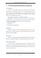
Guilin Feiyu Electronic Technology Co., Ltd 1. FY-41AP Autopilot & OSD System Introduction FY-41AP Module FY-41AP is an inertial attitude measurement instrument used for FPV flight on fixed-wing aircrafts and multi-rotors aircrafts. It has an integrated OSD video overlay system that presents critical flight information such as power management, airspeed, altitude, and flight direction via its electronic compass, allowing for a clear visual flight while ensuring key information is within sight.
Guilin Feiyu Electronic Technology Co., Ltd 2. Function Introduction Altitude Stabilized Mode 41AP can auto stabilize the aircraft flight altitude in this mode. Keep the pitch and roll stick in center position for 0 °altitude. The pitch and roll stick has an endpoint of 45 ° and has linear control over the flight altitude, with a maximum angular velocity of 150 °/ s. The yaw stick in the center position will lock on to the current course.
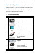
Guilin Feiyu Electronic Technology Co., Ltd OSD Video Overlay Display Function First Person View (FPV): FY-41AP has an integrated OSD video overlay system, so you do not need to connect an external video overlay module. The flight data overlays to video output and through the video transmission system to send back the signal, letting you enjoy the fun of FPV. And operating FPV is even easier with the functions of automatic balance, Hovering, and Auto Return To Launch. 3. FY-41AP Configuration NO.
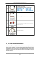
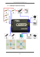
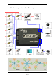
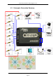
Guilin Feiyu Electronic Technology Co., Ltd 6 2×4P RC receiver wiring For connecting the FY-41AP and RC receiver Black&white——AIL Orange——ELE Green——THR Yellow——RUD Brown——CH5 Blue——CH6(Not use) 7 For connecting the video camera or video transmitter Can weld to power manager module for connecting the battery and ESC 8 9 GPS extension wire 4. FY-41AP Connection Summary The following pictures display the rotation direction and serial number of each motor.
Guilin Feiyu Electronic Technology Co., Ltd 4.1 Roll Quadcopter Connection Summary Pitch Guilin Feiyu Electronic Technology Co., Ltd http://www.feiyu-tech.com Page 6 service@feiyu-tech.
Guilin Feiyu Electronic Technology Co., Ltd 4.2 Roll Hexacopter Connection Summary Pitch Guilin Feiyu Electronic Technology Co., Ltd http://www.feiyu-tech.com Page 7 service@feiyu-tech.
Guilin Feiyu Electronic Technology Co., Ltd 4.3 Octocopter Connection Summary Guilin Feiyu Electronic Technology Co., Ltd http://www.feiyu-tech.com Page 8 service@feiyu-tech.
Guilin Feiyu Electronic Technology Co., Ltd 5.
Guilin Feiyu Electronic Technology Co., Ltd Connect the USB data cable to UART1 port to firmware upgrade for FY-41AP control module Connect the USB data cable to UART2 port to firmware upgrade for OSD module Data link wire Connect the FY-602 data radio to UART1 port Vibration absorbing pads (dampers),use for FY-41AP vibration damping installation. 6. Main Module Installation 6.
Guilin Feiyu Electronic Technology Co., Ltd performance of Hovering mode. Regarding 41AP module installation position, the center of the aircraft should be as far away as possible from other objects that could cause interference. The aim is to reduce the disturbance to the internal IMU position sensors when the aircraft tilts or rotates. In addition, you also have to consider a very important factor: reducing the interference to the 41AP internal magnetic sensor due to positioning during installation.
Guilin Feiyu Electronic Technology Co., Ltd GPS module should be placed as far as possible to the center position, in order to reduce the interference to GPS data when it level rotating. Also you can put the GPS module to a high place using a stent. This practice can effectively reduce the interference to GPS signals caused by other devices, and improve the positioning performance of GPS module. 6.
Guilin Feiyu Electronic Technology Co., Ltd SW1 Attitude Stabilized Mode Hovering Mode Auto Return To Launch Mode(RTH) 8. Gyroscope Reset If the following conditions occur, the FY-41AP initialization is recommended: 1. The device has not been used for a long time. 2. There is a change in environmental temperature of over 30 degrees since last flight. 3. The Red LED flashes continuously even when the FY-41AP remains stationary and you never activate the motor.
Guilin Feiyu Electronic Technology Co., Ltd Combination Stick Commands (CSC) and do the gyro reset. The compass calibration value will be saved into FY-41AP through the gyro reset procedure. 10. FY-41AP Indicator Light Instruction FY-41AP with three colors LED which can send out red, blue, green light. Also yellow, white, purple and other colors light through the combination. Operators can know the FY-41AP‘s operating mode by judging the different colors which the LED sends out and the flash frequency.
Guilin Feiyu Electronic Technology Co., Ltd correctly identify the USB -TTL data cable, then you will find there is more than one port(COM and LPT). If the USB data cable you have received is the new one(Silver), like the picture show, please download the ―Feiyu Tech New USB Driver ‖.The new port is ―Silicon Labs CP210x USB to UART Bridge‖. If the USB data cable you have received is the old one(Black), like the picture show , please download the ― USB Driver ‖.
Guilin Feiyu Electronic Technology Co., Ltd 13. FY-41AP Setting And Debugging After FY-41AP system has been installed and connected, you can adjust settings for the FY-41AP, follow the steps below. 13.1 Direction Setting First of all, according to the direction of the FY-41AP install atio. Guilin Feiyu Electronic Technology Co., Ltd http://www.feiyu-tech.com Page 16 service@feiyu-tech.
Guilin Feiyu Electronic Technology Co., Ltd 13.2 Motor Mixer The following pictures display the rotation direction and serial number of each motor, each ESC should be connected to the DoS&41AP S1 - S8 interface. Pay attention that once you‘ve chosen the control type, the corresponding position motor rotation direction has to be completely the same as in the picture.
Guilin Feiyu Electronic Technology Co., Ltd order to start motors. (Please do not install propeller yet.) Meet the following conditions: Put Throttle stick to the lowest position Put Aileron stick to any endpoint position Put Elevator stick to any endpoint position Put Rudder stick to any endpoint position Please slowly push the throttle and according to the picture ―Motor Mixer‖ shows to check the motor rotation direction is right or not.
Guilin Feiyu Electronic Technology Co., Ltd the pictures found in the ―Motor Mixer‖ section on page 20 of this manual. 13.6 Check The Control Direction Of RC Corresponding Channel After installation is complete, please execute Combination Stick Commands (CSC) in stabilized mode or in Hovering mode (Can not in Auto Return To Launch Mode(RTH) ) to start motors. Slowly push the throttle but do not take off.
Guilin Feiyu Electronic Technology Co., Ltd Control P: If the reaction of multi-rotor in this procedure is too soft (large delay), please increase the basic gain slowly (10%-15% each time) until vibration emerges after you release the stick. Then decrease the gain a little until vibration just disappears. Now the gain should be perfect. Control I: This value generally does not need adjustment.
Guilin Feiyu Electronic Technology Co., Ltd 13.10 Auto Return To Launch Mode(RTH) Test First you should wait until the GPS positioning LED shows that the GPS positioning is in a good condition (Green light double flash each loop or triple flash each loop) so you can get a good hover effects. The GPS will record the first positioning success point as ―Home Point‖. Assuming the GPS hovering mode test is complete, we can now test the auto return to launch function.
Guilin Feiyu Electronic Technology Co., Ltd The default Gimbal Gain:Roll 50,Pitch 50. Under the condition of servo no rotation, you should control the camera gimbal with the RC stick. If the servo is shaking when the stick in the neutral position, that‘s indicates the sensitivity is too much. As a result, you should slowly decrease (10% -20% each time) corresponding direction Gimbal Gain, until the shaking situation disappears. If the camera gimbal goes back to Neutral, it is too soft.
Guilin Feiyu Electronic Technology Co., Ltd After setting the aircraft is powered off, check if it has successfully entered the return mode. Pay attention to safety, to prevent the Failsafe motor rotation, met items cause damage. After each setting, do not forget the "Save parameters" 14. Flight Essentials To achieve satisfactory results, you need to pay attention to the following aspects 1.
Guilin Feiyu Electronic Technology Co., Ltd (2) 1) Please control your aircraft fly 0.8 meters above to the ground, which will give you a good control effect. And if you control your aircraft descend to the ground in hovering mode may cause the aircraft altitude volatility which caused by the ground air. 2) Without the GPS module, switching to Hovering Mode or Auto Return to Launch Mode will automatic bring you into Fixed Altitude Flight Mode.
Guilin Feiyu Electronic Technology Co., Ltd 6 Distance to Home Point (Unit: m) 15 7 Power battery current (Unit: A) 16 8 Flight mode 17 9 Current latitude & longitude of the plane (Format: dddmm.mmm) The angle of turning to the Home Point (Unit: deg) Attitude table Relative position of Home Point (Icon in the middle position when the aircraft is around Home Point.
Guilin Feiyu Electronic Technology Co., Ltd —— END —— Note: We reserve the right to change this manual at any time! And the newest edition will be shown on our website www.feiyu-tech.com. Guilin Feiyu Electronic Technology Co., Ltd http://www.feiyu-tech.com Page 26 service@feiyu-tech.