
Installation Guide

SEAM TREATMENT OPTIONS
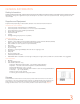
Before starting, determine which seam treatment is being used.
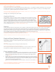
Moldings
One-piece moldings with expansion control guides or two-piece moldings are available for
installation with standard frp wall panels. Panels are inserted into the one-piece molding opening,
while both parts of the two piece molding are installed on top of the panel
(Figure 7). Panels beneath
the two-piece molding should maintain the recommended expansion spacing. FRP adhesive should
be used when installing moldings. Do not apply silicone to install. Installations requiring additional
abuse resistance should use the heavy-duty corners and batten strip.
Installation of panels over 12 feet long is not recommended.
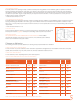
EXPANSION JOINT CHART
* For tile-look decorative panels, use a six penny nail for joint spacing.
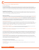
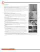
USING MOLDINGS
1. Start in an inside corner. Mark plumb line 48-1/8” (1.2 m) from corner. The first panel
should be set true with a plumb line.
NOTE: If the panel is supplied with a protective tack film, leave film on during installation. Peel
back tack film approximately 1/2” (12.7mm) for easy insertion into moldings. Remove film after
installation.
2. Place first panel against wall and align leading edge with plumb line.
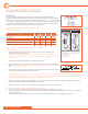
3. Insert a division bar on the first panel up to expansion control guide and continue installing
panels.
The free edge of the molding or division bar may be tacked in place if preferred before
installing next panel.
(Figure 9)
4. Use a laminate roller to ensure all air pockets are removed between the panel and the wall and
to ensure a good bond between the panel and the wall.
NOTE: If using cap at the top or bottom of panel, slide it completely on to panel and maintain recommended expansion spacing. When
not using cap at top and bottom, leave 1/4” (3.2 mm) gap for expansion. If a moisture resistant installation is required, silicone sealant
should be applied in all moldings and around all panel edges, fasteners and fixtures.
5. Install the last panel on the first wall as stated above, but with no corner molding on the leading edge. The first panel on the new wall
will receive a corner molding, thus completing the corner transition.
6. Slide the next panel into the division bar. Repeat process working in one direction around the room.
IMPORTANT—NOTES REGARDING TILE LOOK PANEL INSTALLATION
1. For proper alignment of the horizontal score lines, create a level line from the highest area of the floor.
2. Plan your panel layout so that the seams of the panels are not directly over the seams of the substrate. Avoid positioning joints close to
inside or outside corners.
3. Keep tack film on during installation to protect the panels—peel back approximately 1/2” for easy installation into trims.
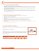
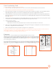
3/8”
1
4
“
1/4”
1/4”
1
4
“
WRONG
RIGHT
WRONG: No clearance at ceiling and
floor; fastener holes are tightly fit (same
size as fastener).
RESULT: When the room is put into
operation, an increase in temperature
and/or humidity may cause normal
panel expansion. Since the panel fits
too tightly, there is no place for it to
expand. It is likely that the panel will
bulge between fasteners.
RIGHT: Adequate clearance at wall and
floor. Over-sized fastener holes.
RESULT: Panel will expand normally
and stay flat. Sealant will absorb the
movement and a proper seal will be
retained.
1/2”
FIGURE 8
FIGURE 7
FIGURE 9
Panel Size 4’ x 8’ 4’ x 9’ 4’ x 10’ 4’ x 12’
Gap at Ceiling 1/4” 1/4” 3/8” 3/8”
Gap at Floor 1/4” 1/4” 3/8” 3/8”
Gap Between Panel and Center of 1 Piece Molding 1/8” 1/8” 3/16” 3/16”
Gap Between Panel and Center of 2 Piece Molding 1/4” 1/4” 3/8” 3/8”
Gap Between Panel When Not Using Moldings * 1/4” 1/4” 3/8” 3/8”
installation guide