
Installation Guide

PRE-INSTALLATION PLANNING
• Pre-fit each panel before fastening and/or adhering in place.
• All cutting and drilling should be done prior to the application of adhesive.
• Preplan for cove or base molding. FRP panels should be installed so that the bas e molding will not restrict normal panel movement
during expansion and contraction. Cut panels 1/4” short of where the base molding will extend; poured acrylic floor with built-in base
cove should be in place prior to installation.
• When using rivets, pre-drill holes in the panels using a drill bit that is 1/4” larger than the rivet. Plan ahead so that fasteners will not
interfere with moldings or other wall fixtures.
• When using mechanical fasteners through FRP to attach wall angles or other fixtures, pre-drill holes using a drill bit that is 1/4” larger
than the mechanical fastener. Without oversizing the holes, the FRP will likely have bulges and/or buckles when panel movement
occurs during expansion and contraction.
BASIC FRP INSTALLATION STEPS
1. Trim panel to fit. Oversize pilot holes if drop-in ceiling wall angle is attached to and through FRP
(please allow for proper expansion and contraction)
2. Radius corners of any cut out fixture openings.
3. Apply adhesive to 100% of the backside of panel using a cross-hatch pattern using a trowel recommended by the adhesive
manufacturer.
4. Place panel on wall, leaving appropriate room at panel joints and corners for expansion and contraction.
5. Using a laminate roller, remove air pockets by rolling down and out toward the panel edge without a molding.
6. Fit appropriate moldings to panels edge leaving a minimum of 1/8” for expansion between panel and molding stem.
7. Install next panel.
The nature of FRP panels is to expand and contract. Without leaving required room for expansion and contraction, FRP panels can develop
buckles and/or bulges because panel movement will occur.
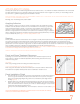
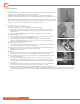
CUTTING INSTRUCTIONS
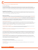
POSITION PANEL FACE DOWN ON A COVERED WORK AREA
When cutting with a circular saw, position the panel so that the saw blade enters the back side of panel first to avoid chipping or damage.
(Figure 3)
Radius Corners of Cut-Outs
CUT-OUTS
The inside corners of all cut-outs must have a radius of at least 1/8” (3.2 mm). Failure to radius corners
may result in stress cracking. For pilot holes, a 1/4” (6.36 mm) diameter router bit or drill bit may be
used, use a jig saw to complete the radius cut out. Allow 1/8” (3.2 mm) clearance around all fixtures,
electric boxes, piping, etc.
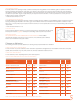
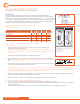
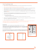
EXPANSION JOINT CHART
Optional Shear
Front Side
FIGURE 3
Panel Size 4’ x 8’ 4’ x 9’ 4’ x 10’ 4’ x 12’
Gap Around Rivets 1/8” 1/8” 1/8” 3/16”
Gap Between Panels and Wall Fixtures 1/8” 1/8” 1/4” 1/4”
installation guide