
User Manual
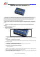

AEO TECHNOLOGY www.AEOrc.com
Entire Contents © Copyright 2010
3
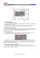
3. Operating:
3.1 Select mapping mode:
We have two kinds of mapping modes.
Users can store two different kinds of operating modes ,through manual calibration can switch between
the two operating modes.(refer to 4.4)。
”MODE 1” represents the recent chosen mode ,you can control every channel of the receiver refer to
3.3 below .when switch to ”MODE 2”,control channels of the receiver refer to 3.3 under mode 2.
3.2Select head tracking system reset:
When System1.5 is connected with head movement tracking system ,you can set any channel on the
transmitter as the reset button . RST SW= BTN represents that push the button on system1.5 down ,you can
also choose other ways to reset the heading tracking system by setting it yourself.
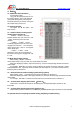
3.3Select mapping channel:
“CH1、CH2、CH3、CH4…CH8”,represents that in recent mode ,receiver’s every channel is
controlled by transmitter’s output signal channel as set(as the following picture shows)
For example:“CH1”represents the first channel of the receiver is controlled by some channel
connected to the interface ,you can set “CH1”as any channel ,if you set it as B1,the it is controlled by the
first output channel connected to interface B .set asD5,then controlled by the fifth channel connected to
interface D . CH2-CH8 are just as the same.
3.4 Head movement tracking system warning :
It shows whether the head movement tracking system is connected right .when not connected or
connected wrongly, it wiil display “LINK ERROR!”when connected rightly and work normally,“LINE
ERROR!”turns into “WWW.AEORC.COM”