
User Manual


Installation
4
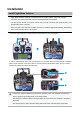
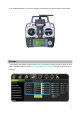
Install Flight Mode Switcher
2
1
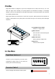
Flight Mode Switcher should be c
onnected to the RC System before using. And improper
connection can result in abnormal work even causing damage to the switcher.
The RC System should have spare channel ratio (usually connected with potentiometer), and
provided with power of 5V/3.3V.
Users can refer to this instruction of cable connection to install the Flight Mode Switcher, exampled by
the V1 knob channel in WFLY7 RC System.
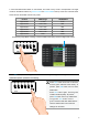
1. Plug the top left knob out on the RC System; Unpack the back cap of RC System.
·
·
·
· Please don’t judge the denition of proportional channel by color. Use multimeter to conrm the
power, signal and ground electrode on connection cables.
· The denition of switcher: White is the signal cable, red is the power line, and black is the ground
electrode.
· You should pull a 5V power cable from RC System when some channels haven’t power lines.
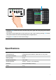
2. Pull the potentiometer down, and use the electric iron to solder down the potentiometer connection
c
able. Solder switcher connection cable to corresponding potentiometer cable. Do the insulate
protection by heat shrink tube or insulating tape.