
User Manual
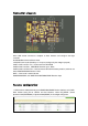

Connection diagram:
Micro USB socket: Connect to computer to flash firmware and configure the flight
controller
M1/M2/M3/M4:Connect to Brush motor
VCC/GND: Connect to the battery 1s~2s input (Configure by the voltage input pad)
UART1: GND +5V RX1 TX1 , Could connect to GPS/OSD
UART2: GND +5V RX2 PPM/SBUS Receiver input(RX2)
UART3: GND +5V RX3 TX3 Could connect to GPS OR Telemetry module ,could not use
when DSM/DSM/DSMX Receiver Used
BUZ+ -: Connect to a external buzzer
DSM/DSM2/DSMX: 3.3V GND RX3 DSM/DSM2/DSMX Receiver input
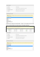
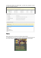
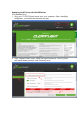
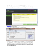
Receiver configuration:
1. DSM receiver soldered directly to the DSM/DSM2/DSMX Receive interface 3.3V, GND,
RX3. Enable Seria_RX for UART3 and Set Receiver mode RX_SERIAL ,Select
Spektrum1024(DSM/DSM2) or Spektrum2048(DSMX) in Cleanflight configurator.