
Manual


4
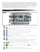
Power Supply Installation
WARNING: AC power wiring must be installed and connected by qualied personnel only. All electrical components and installation
procedures must comply with all applicable local and national electrical codes. Some codes may require a means of disconnecting from the
AC power source installed in the xed wiring and having a contact separation of at least 0.120" (3mm) in the line and neutral poles. Make
sure the power source is OFF prior to connecting the controller. If the supply cord is damaged, it must be replaced by the manufacturer,
its service agent or a similarly qualied person in order to avoid a hazard.
WARNING: is appliance is not intended for use by persons (including children) with reduced physical sensory, or mental capabilities,
or lack of experience and knowledge, unless they have been given supervision or instruction concerning use of the appliance by a person
responsible for their safety. Children should be supervised to ensure that they do not play with the appliance.
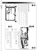
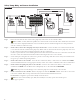
Indoor and 240 VAC Outdoor Models
Indoor models and the 240 VAC Outdoor model will be pre-wired with a power cord
Figure 6
ready to be plugged into a wall power socket.
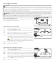
110 VAC Outdoor Models (US and Canada)
Step 1 – Route power and ground wires from a power source through a conduit
Figure 7
Black White Green
110 VAC Outdoor Models
and into the EVOLUTION
®
cabinet.
Step 2 – Open the EVOLUTION
®
controller and access the internal components.
Step 3 – Remove the power compartment cover to access the transformer wiring.
Remove 1/2" (12.7mm) of insulation from the wire ends.
Step 4 – Using the provided wire nuts, secure the transformer Line (black) wire
to the black power source wire, Neutral (white) to the white power source
wire and Equipment Ground wire (green) to the green power source wire.
Note: Earlier EVOLUTION
®
model is equipped with two Equipment
Ground wires (green). Connect both wires to the green power source wire.
Step 5 – Install and secure the power compartment cover.
Step 6 – Apply power to the controller.
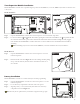
220 VAC Outdoor Models (Outside US and Canada)
Step 1 – Route power and ground wires from a power source through a conduit
Figure 8
Brown Green/Yellow Blue
(L) (N)
(
)
220 VAC Outdoor Models
and into the EVOLUTION
®
cabinet.
Step 2 – Open the EVOLUTION
®
controller and access the internal components.
Step 3 – Remove the power compartment cover to access the transformer terminals.
Step 4 – Remove 1/2" (12.7mm) of insulation from the power source wire ends and
install the brown wire into the Line (L)terminal. Install the green wire into
the Ground ( ) terminal and the blue wire into the Neutral (N) terminal.
Step 5 – Install and secure the power compartment cover.
Step 6 – Apply power to the controller.