
Manual


146
DXi User Manual
Appendix F: Grounding the Communication Cable
Prepping the Chassis
Methods 2 and 3 might require installing a ground nut into the controller chassis.
Follow these directions carefully to ensure grounding and chassis water rating are not
compromised.
1. Drill hole location. The ground nut should be installed within 12 cm of the
terminal blocks of the DX output board. On the interior, the drill hole should be
as unobstructed and clear of interior cards and cables as possible.
2. Drill a 1/4” hole. Have on hand a stainless-steel flathead machine screw (1/4-20)
x 3/4” that engages at least two full threads.
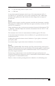
3. Use the diagram, right, to install the screw and the various washers, lock washers,
ring terminals, and nuts.
To crimp the ground wires into the ring terminals, follow Ring Terminal
instructions, right.
Be sure that washers are installed on both sides of the chassis wall to
ensure water cannot ingress.
4. Secure ring terminals with washer, lock washer, and lock nut.
chassis wall
1/4-20 3/4”
screw or bolt
lock washer
lock nut
washer
washer
washer
lock washer
1/4” nut
ring
terminal/s
Ring Terminal Specifications
Part number: 415-0210: MPN 711K818
Crimping Instructions:
1. Mount the terminal on a threaded screw or stud for a secure
connection.
2. Use a wire crimper (McMaster part 7289K1 or similar) to
fasten ground leads to wire. Place crimp end into the die of
the tool with ground leads passing through. Apply pressure
on the crimp until ground leads are securely fastened into the
crimping end of the terminal.