
Manual


128
DXi User Manual
Appendix D: Setting Up a FLOW MAX System
Submaster Setup Procedure
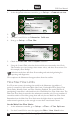
1. At the designated submaster controller, go to Setup-->Communication.
2. to turn on Submaster.
3. Use the Control Dial to set Submaster Address.
4. Now go to Setup-->Flow Max.
5. Check the FLOW MAX Participant checkbox.
6. Using the Control Dial, select the devices which are connected to this Clock.
This includes up to two pumps, three master valves, and three flow sensors. For
this example, select Pump 1.
Selections made here will allow flow tracking and statistical gathering for
reporting and diagnostics.
This completes the Submaster Setup procedure from the satellite.
Flow Max Flow Limits
In a Flow max system, the settings that reside in the Submaster (regardless of
point of connection) will control Main Line Limit, Unscheduled Flow Limit, Flow
Check Delay, Monthly Limit, and Flow Checking Enabled. The total GPM for all
participating controllers is calculated into the overall Main Line Flow Limit value. The
Main Line Flow Limit is entered at the submaster controller only. For any number of
controllers within a Flow Max group, there will only be one Main Line Flow Limit.
Remember that the Main Line Flow Limit must be higher than an expected flow
under normal operation yet low enough to react when a main break occurs.
Set the Main Line Flow Limits
1. At the submaster controller, go to Setup-->Flow-->Flow Options.
2. Use the Control Dial to enter the appropriate Main Line Limit value.
FLOWMAX Participant
Devices Connected to this Clock:
Pumps: 1 2
Master Valves: 1 2 3
Flow Sensors: 1 2 3
Setup FLOWMAX WED 5:43:40 PM
Submaster
Comm Option Device:
WiFi
Submaster Address: 240
Cloud Connect: Off
Setup Communication WED 5:43:40 PM
|Submaster|ENET|WiFi|M7/8|Cell
Monthly Limit 9999999
Main Line Limit 0500
Unscheduled Limit 0000
Flow Check Delay (m) 2
Setup Flow Options WED 5:43:40 PM
|Limits|Monitoring|