
Manual


106
DXi User Manual
Appendix B: Flow Sensors
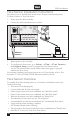
Flow Sensor Installation Instructions
The plastic cover of the DXi main board shows all inputs and terminal polarity.
To install a Irritrol or Toro flow meter:
1. Power down the DXi controller.
2. Connect the white and black wires as shown.
3. Return power to the controller.
4. To configure the flow sensor, go to Setup-->Flow-->Flow Sensors.
See Chapter 4: Setup on how to navigate the Flow Sensors screen.
Use the "Flow Meter Offset and K Values" tables (next page) to properly
calibrate the flow sensor.
For complete installation and setup instructions of a Flow decoder, refer to Toro
document 373-1022, TW-DAC-FLOW Decoder Installation Guide.
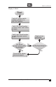
Flow Sensor Overview
To establish flow limit checking either on a controller or individual station basis,
verify the following:
• Flow meter is installed properly.
• Correct Offset and K values are entered.
• Station Upper Limits have been established. See "Max Flow Limit".
• Station Lower Limits have been established. See "Min Flow Limit".
• Main line flow limits have been established. See "Main Flow".
• Total Monthly Flow has been set. See "Flow Options".
• Unscheduled Flow Limit has been defined. See "Unscheduled Flow Limit".
• Upper and lower limit checking is enabled.
See "Enable/Disable Limit Checking".
• The appropriate flow limit check delay has been established. See "Delay Limit".
• Selection of at least one of the three flow meters.
FLOW 1”
MV1 MV2 MV3 P1 P2
24
VAC COM COM COM
FLOW/SENSORS/ALARM
1 2 3 1 2 3 4 5 6
1 2 3 1 2
OFF
FLOW AUX.SENSOR INPUTS MV PUMP
+ - + - + - + - + - + - + - + - + - + + + + + - - -
2 WIRE
24
VAC
F2
5V
12V
3.5V
24VAC
COMMON
DX3 MAIN BOARD
white to +
black to -
CST flow meter