
User Manual


portion of Section 3.c for more information on selecting appropriate motors.
* Note for Due users: The voltage on the current sense pins will exceed the Due’s 3.3 V
limit when the current draw exceeds ~23 A. The Due should generally be able to handle this
since the MCU’s integrated protection diodes will clamp the input voltage to a safe value
(and since the CS circuit has a 10 kΩ resistor in series with the output, only a few hundred
microamps at most will flow through that diode). However, if you really want to be safe, you
can use a 3.3 V zener diode to clamp the current sense output voltage to a maximum of
~3.3 V. If you want to get the full range of current feedback while using the Due, you can
disconnect the shield’s current sense pins from the Due and then reconnect them through a
voltage divider; see Section 6.a for more information.
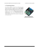
3.b. Assembly for Use as an Arduino Shield
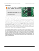
1. Stackable Arduino headers: Before you can use this board as an Arduino shield, you need
to solder four of the five included Arduino header strips to the set of holes highlighted in red
in the picture above. The headers should be oriented so that the female sockets rest on the
top side of the shield and face up while the male pins protrude down through the board,
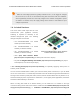
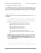
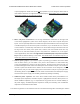
and the solder connections should be made on the underside of the shield. The newest
Arduino boards, including the Uno R3 and the Leonardo, use one 10×1 header, two 8×1
headers, and one 6×1 header, as shown in the left picture below; older Arduino boards use
two 8×1 headers and two 6×1 headers, as shown in the right picture below (the two pairs
Pololu Dual VNH5019 Motor Driver Shield User’s Guide © 2001–2017 Pololu Corporation
3. Getting Started with an Arduino Page 8 of 35