
User Manual

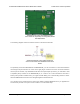

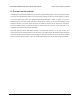

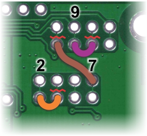
Arduino pin remapping of dual
VNH5019 motor driver shield for
single-channel mode (view of
underside of PCB).
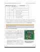
PWM INA INB OUTA OUTB operating mode
0 0 0 OPEN OPEN coast
0 1 0 H OPEN coast “clockwise”/brake “counterclockwise”
0 0 1 OPEN H coast "counterclockwise/brake “clockwise”
0 1 1 H H brake high (to VOUT)
1 0 0 L L brake low (to GND)
1 1 0 H L drive “clockwise”
1 0 1 L H drive “counterclockwise”
1 1 1 H H brake high (to VOUT)
The above truth table assumes that both motor drivers are enabled and are not experiencing a fault
condition (i.e. M1EN/DIAG and M2EN/DIAG pins are low). Otherwise, the disabled output will be
“open” (high-impedance). Note that in this new configuration, the M1EN/DIAG pin effectively becomes
a new ENA/DIAGA pin and the M2EN/DIAG pin effectively becomes a new ENB/DIAGB pin.
Note: In single-channel mode, the current sense feedback is disabled and the motor
indicator LEDs do not illuminate.
Arduino Shield Modifications
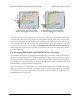
If you are using this motor driver as an Arduino shield and
want to reconfigure it for single-channel mode, we
recommend you physically modify the Arduino pin mappings
(general information on this is available in Section 6.a). While
the reconfiguration could be done completely in software,
doing so makes it very easy to accidentally command the
motor drivers to create a short circuit that could damage
something, so we advise against this approach. Instead, we
recommend you do the following (in order):
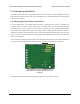
• Disconnect Arduino pins 4, 8, and 10 from driver pins
M1INB, M2INB, and M2PWM, respectively, by cutting
the appropriate traces on the underside of the PCB
with a knife. The thin, red, wavy lines in the picture to
the right show where to cut. (You can restore these
Pololu Dual VNH5019 Motor Driver Shield User’s Guide © 2001–2017 Pololu Corporation
7. Using the Driver in Single-Channel Mode Page 31 of 35