
User Manual


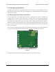

Dual VNH5019 motor driver shield:
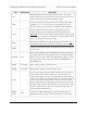
Arduino pin mappings for motor driver
1.
Dual VNH5019 motor driver shield:
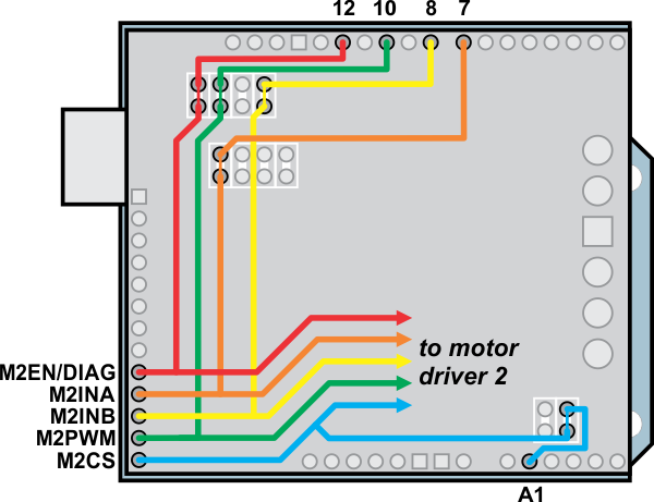
Arduino pin mappings for motor driver
2.
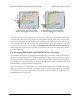
In all cases, the top through-hole of the pair connects to the Arduino pin and the bottom through-hole
connects to the motor driver pin. To change one of the default mappings, simply use a knife to cut the
trace between the appropriate pair of holes on the underside of the PCB (there is no connection to cut
on the topside of the PCB) and run a wire from a different Arduino pin to the bottom hole of the pair
to create a new connection. You can later use shorting blocks [https://www.pololu.com/product/968] to
restore the default pin mapping if you populate the severed hole pairs with 2×1 pieces of the included
0.1″ male header strip.
6.b. Accessing ENA/DIAGA and ENB/DIAGB Pins Separately
The VNH5019 motor drivers have separate enable/diagnostic pins for the A and B half bridges, but
the shield combines these lines into a single enable/diagnostic pin for each motor driver in order to
decrease the number of I/O lines required to monitor motor faults. This combined line is sufficient for
most applications, but you can modify the board to get independent access to MxENA/DIAGA and
MxENB/DIAGB if you want the additional information.
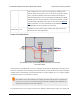
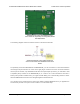
There are two pairs of 0.1″-spaced holes on the shield labeled “M1EN A=B” and “M2EN A=B”. These
pairs are connected on the underside of the PCB by a thin trace, with the hole labeled “A” connecting
to the ENA/DIAGA pin of the corresponding motor driver and the hole labeled “B” connecting to the
ENB/DIAGB pin of the motor driver:
Pololu Dual VNH5019 Motor Driver Shield User’s Guide © 2001–2017 Pololu Corporation
6. Customizing the Shield Page 28 of 35