
User Manual


6. Customizing the Shield
This motor driver shield has several features that will not be useful in a typical application but that
might benefit an advanced user. This section explains how to modify the shield from its default state
to access these features.
6.a. Remapping the Arduino Connections
For some applications, this shield’s default Arduino pin mappings might not be convenient. For
example, maybe you want to use the 16-bit Timer 1 for making music on a buzzer and would rather
use PWMs from Timer 0 to control your motor speed. Or maybe you don’t care about monitoring the
motor current and would rather use all of your analog inputs for reading sensors. With this in mind, we
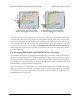
designed the shield to have break points in the connection between the Arduino pins and the motor
drivers. It is easy to cut the connections at these points and establish new connections to replace the
broken ones if desired.
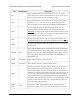
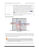
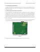
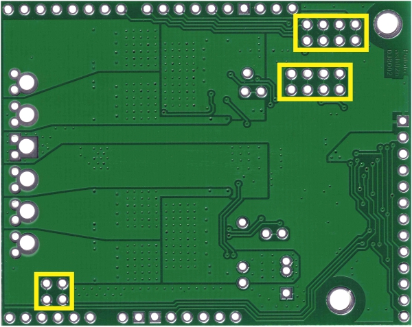
The connections between the Arduino pins and the VNH5019 motor driver pins are each made through
a pair of 0.1″-spaced holes that are connected on the underside of the shield by a thin trace:
Cuttable traces on the dual VNH5019 motor
driver shield for changing default Arduino pin
mappings.
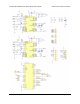
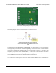
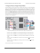
The following two diagrams show the default pin mapping for motor drivers 1 and 2:
Pololu Dual VNH5019 Motor Driver Shield User’s Guide © 2001–2017 Pololu Corporation
6. Customizing the Shield Page 27 of 35