
User Manual


high enabling the motor outputs and a logical low disabling motor
outputs. When a driver fault occurs, the IC drives this pin low and the
motor outputs are disabled. Note that the VNH5019 actually has
separate EN/DIAG pins for each half bridge (ENA/DIAGA and ENB/
DIAGB), but these are tied together on the board by default to create
a single enable input/diagnostic output for each driver. See Section
6.b for information on how to individually access ENA/DIAGA and
ENB/DIAGB pins (this is typically not necessary).
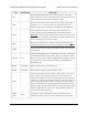
MxCS_DIS LOW
Disables the current sense output, MxCS, when high. Can be left
disconnected in most applications.
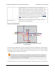
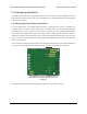
Power Considerations
Dual VNH5019 motor driver shield power buses when not used with
an Arduino shield.
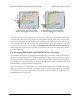
The shield must be supplied with 5.5 to 24 V through the large VIN and GND pads on the right side of
the board. A high-side reverse-voltage protection MOSFET prevents the shield from being damaged
if shield power is inadvertently connected backwards (for supply voltages up to 16 V; higher voltages
can damage the driver if connected in reverse).
Note that the motor driver features over-voltage protection that can kick it at voltages as
low as 24 V, so we do not recommend using it with 24 V batteries (such batteries can
significantly exceed 24 V when fully charged).
It is important that you use a power source that is capable of delivering the current your motors will
Pololu Dual VNH5019 Motor Driver Shield User’s Guide © 2001–2017 Pololu Corporation
4. Using as a General-Purpose Motor Driver Page 22 of 35