
User Manual
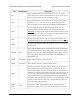


PIN Default State Description
VIN
The connection point for the positive side of the 5.5 – 24 V motor
power supply. Since the overvoltage protection can be as low as 24 V,
we do not recommend using 24 V batteries for VIN.
VDD
The connection point for the positive side of the logic power supply
(typically 2.5 – 5 V). The only function of this pin is to power the
internal pull-ups on the enable lines, M1EN/DIAG and M2EN/DIAG.
VOUT
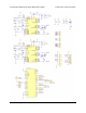
This pin gives you access to the motor power supply after the
reverse-voltage protection MOSFET (see the board schematic in
Section 5). It can be used to supply reverse-protected power to other
components in the system, but it should not be used for high currents.
This pin should only be used as an output.
GND
Ground connection points for logic and motor power supplies. The
controlling device and the motor driver must share a common ground.
MxA/B
Output of half-bridge A/B. Each half-bridge connects to one terminal
of a DC motor.
MxPWM LOW
Pulse-width modulation input: a PWM signal on this pin corresponds
to a PWM output on the corresponding driver’s motor outputs. When
this pin is low, the motor outputs are high impedance. When it is high,
the output state is determined by the states of the MxINA/B and
MxEN/DIAG pins.
MxINA FLOATING Motor direction input A (“clockwise” input).
MxINB FLOATING Motor direction input B (“counterclockwise” input).
MxCS
Current sense output. The pin voltage is roughly 140 mV per amp of
output current when the CS_DIS pin is low or disconnected. The
current sense reading is more accurate at higher currents. (Note that
while the CS voltage can potentially exceed 3.3 V at high currents, the
current sense circuit should be safe for use with many 3.3V analog
inputs. Most MCUs have integrated protection diodes that will clamp
the input voltage to a safe value, and since the CS circuit has a 10 kΩ
resistor in series with the output, only a few hundred microamps at
most will flow through that diode.)
MxEN/
DIAG
HIGH
Combination enable input/diagnostic output. When the driver is
functioning normally, this pin acts as an enable input, with a logical
Pololu Dual VNH5019 Motor Driver Shield User’s Guide © 2001–2017 Pololu Corporation
4. Using as a General-Purpose Motor Driver Page 21 of 35