
User Manual


925] should be soldered directly to the board.
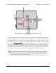
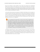
3. Additional power capacitor: The motor driver shield includes three pre-installed 47 uF
electrolytic power capacitors, and there is space—highlighted in blue in the above picture—to
add an additional capacitor (e.g. to compensate for long power wires or increase stability of
the power supply). An additional power capacitor is usually not necessary, and no additional
capacitors are included with this shield.
With the exception of the pins labeled “MxEN A=B” and “MxCS_DIS”, all of the through-holes not
highlighted in the above diagram are only relevant when using this driver as an Arduino shield. The
“MxEN A=B” and “MxCS_DIS” pins are explained in the “Pinout” portion of Section 4.b, but they will
not be needed in typical applications and can generally be ignored.
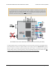
4.b. Board Connections
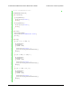
Dual VNH5019 motor driver shield connected to a microcontroller (gray connections are
optional).
The above diagram shows the minimum connections typically required to interface this motor driver
with a microcontroller.
Pinout
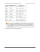
The following table explains the board pins in detail. See the VNH5019 datasheet
[https://www.pololu.com/file/download/vnh5019.pdf?file_id=0J504] (475k pdf) for even more detailed
information about these pins, including the truth table that explains how the MxPWM and MxINA/B
pins affect the MxA/B motor outputs.
Pololu Dual VNH5019 Motor Driver Shield User’s Guide © 2001–2017 Pololu Corporation
4. Using as a General-Purpose Motor Driver Page 20 of 35