
User Manual
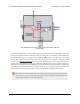
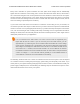


Motor with one 0.1 uF
capacitor soldered across its
terminals.
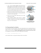
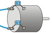
Motor with two 0.1 uF
capacitors soldered from its
terminals to its case.
1. Solder a 0.1 µF ceramic capacitor [https://www.pololu.com/
product/1166] across the terminals of your motors, or solder
one capacitor from each terminal to the motor case (see the
pictures to the right). For the greatest noise suppression,
you can use three capacitors per motor (one across the
terminals and one from each terminal to the case).
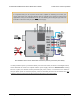
2. Make your motor leads as thick and as short as possible,
and twist them around each other. It is also beneficial to do
this with your power supply leads.
3. Route your motor and power leads away from your logic
connections if possible.
4. Place decoupling capacitors (also known as “bypass
capacitors”) across power and ground near any electronics
you want to isolate from noise. These can typically range
from 10 uF to a few hundred uF.
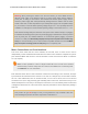
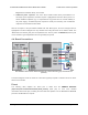
3.d. Programming Your Arduino
Our Arduino library for the dual VNH5019 motor driver shield makes it easy to get started writing your
Arduino sketches. A link to download the library, installation instructions, and the library command
reference can be found on the library’s github page [http://github.com/pololu/dual-vnh5019-motor-shield].
Once installed, we recommend you try out the example sketch by selecting
File > Examples > DualVNH5019MotorShield > Demo
from the Arduino IDE, or by copying the following code into a new sketch:
Pololu Dual VNH5019 Motor Driver Shield User’s Guide © 2001–2017 Pololu Corporation
3. Getting Started with an Arduino Page 16 of 35