Pololu Dual VNH5019 Motor Driver Shield User’s Guide © 2001–2017 Pololu Corporation Pololu Dual VNH5019 Motor Driver Shield User’s Guide 1. Overview . . . . . . . . . . . . . . . . . . . . . . . . . . . . . 1.a. Features . . . . . . . . . . . . . . . . . . . . . . . . . . 1.b. Included Hardware . . . . . . . . . . . . . . . . . . . . 2. Contacting Pololu . . . . . . . . . . . . . . . . . . . . . . . . . 3. Getting Started with an Arduino . . . . . . . . . . . . . . . . . 3.a. What You Will Need . . . . .
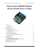
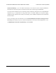
Pololu Dual VNH5019 Motor Driver Shield User’s Guide © 2001–2017 Pololu Corporation 1. Overview This user’s guide focuses on the latest version (ash02b) [https://www.pololu.com/ product/2507] of the Pololu dual VNH5019 motor driver shield, but most of the information also applies to the earlier ash02a [https://www.pololu.com/product/2502] version. See Section 9 for details about the differences between board revisions. The Pololu dual VNH5019 motor driver shield for Arduino [https://www.pololu.
Pololu Dual VNH5019 Motor Driver Shield User’s Guide © 2001–2017 Pololu Corporation • Wide operating voltage range: 5.5 – 24 V1 • High output current: up to 12 A continuous (30 maximum) per motor • Motor outputs can be combined to deliver up to 24 A continuous (60 A maximum) to a single motor (see Section 7) • Inputs compatible with both 5V and 3.3V systems (logic high threshold is 2.
Pololu Dual VNH5019 Motor Driver Shield User’s Guide © 2001–2017 Pololu Corporation 1 While the overvoltage protection typically activates at 27 V, it can trigger at voltages as low as 24 V, so we do not recommend using this motor driver with 24 V batteries, which significantly exceed 24 V when fully charged. If the shield is configured to power an Arduino or Arduino clone, the supply voltage must conform to that Arduino’s input voltage requirements. 1.b.
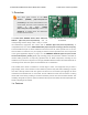
Pololu Dual VNH5019 Motor Driver Shield User’s Guide solderless-breadboards], © 2001–2017 Pololu Corporation or you can solder wires directly to the board for more compact installations. Note that motor and motor power connections should not be made through a breadboard. The motor driver includes three 47 uF electrolytic power capacitors, and there is room to add additional capacitors (e.g. to compensate for long power wires or increase stability of the power supply).
Pololu Dual VNH5019 Motor Driver Shield User’s Guide © 2001–2017 Pololu Corporation 2. Contacting Pololu We would be delighted to hear from you about any of your projects and about your experience with the dual VNH5019 motor driver shield for Arduino [https://www.pololu.com/product/ 2502]. If you need technical support or have any feedback you would like to share, you can contact us [https://www.pololu.com/ directly or post on our forum [http://forum.pololu.com/ contact] viewforum.php?f=15].
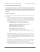
Pololu Dual VNH5019 Motor Driver Shield User’s Guide © 2001–2017 Pololu Corporation 3. Getting Started with an Arduino As with virtually all other Arduino shields, connections between the Arduino and the motor driver are made via extended stackable headers that must be soldered to the through-holes along the top and bottom edges of the shield. This section explains how to use this motor driver as an Arduino shield to quickly and easily add control of up to two DC motors to your Arduino project.
Pololu Dual VNH5019 Motor Driver Shield User’s Guide © 2001–2017 Pololu Corporation portion of Section 3.c for more information on selecting appropriate motors. * Note for Due users: The voltage on the current sense pins will exceed the Due’s 3.3 V limit when the current draw exceeds ~23 A.
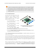
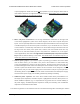
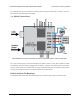
Pololu Dual VNH5019 Motor Driver Shield User’s Guide © 2001–2017 Pololu Corporation of pins highlighted in darker red should not be populated if you are using this board with an older Arduino that does not support these additional pins). Please make sure you solder the appropriate headers for your particular Arduino! 2. Motor and power connections: The six large holes/twelve small holes on the right side of the board, highlighted in yellow in the above diagram, are the motor outputs and power inputs.
Pololu Dual VNH5019 Motor Driver Shield User’s Guide © 2001–2017 Pololu Corporation pin mappings and are not necessary for getting started using this shield with an Arduino. They are discussed in more detail later in this guide. 3.c. Shield Connections Dual VNH5019 motor driver shield with an Arduino (shield and Arduino powered separately). All of the necessary logic connections between the Arduino and the motor driver shield are made automatically when the shield is plugged into the Arduino.
Pololu Dual VNH5019 Motor Driver Shield User’s Guide Arduino Pin VNH5019 Driver Pin © 2001–2017 Pololu Corporation Basic Function Digital 2 M1INA Motor 1 direction input A Digital 4 M1INB Motor 1 direction input B Digital 6 M1EN/DIAG Motor 1 enable input/fault output Digital 7 M2INA Motor 2 direction input A Digital 8 M2INB Motor 2 direction input B Digital 9 M1PWM Motor 1 speed input Digital 10 M2PWM Motor 2 speed input Digital 12 M2EN/DIAG Motor 2 enable input/fault output Anal
Pololu Dual VNH5019 Motor Driver Shield User’s Guide © 2001–2017 Pololu Corporation Dual VNH5019 motor driver shield power buses when connected to an Arduino. In the shield’s default state, the motor driver shield and Arduino are powered separately. When used this way, the Arduino must be powered via USB, its power jack, or its VIN pin, and the shield must be supplied with 5.5 to 24 V through the large VIN and GND pads on the right side of the board.
Pololu Dual VNH5019 Motor Driver Shield User’s Guide © 2001–2017 Pololu Corporation It is important that you use a power source that is capable of delivering the current your motors will require. For example, alkaline cells are typically poor choices for high-current applications, and you should almost never use a 9V battery (the rectangular type with both terminals on the same side) as your motor power supply. Dual VNH5019 motor driver shield with an Arduino (Arduino powered by the shield).
Pololu Dual VNH5019 Motor Driver Shield User’s Guide © 2001–2017 Pololu Corporation Warning: When powering the Arduino from the motor shield, you must never connect a different power supply to the Arduino’s VIN pin or plug a power supply into the Arduino’s power jack, as doing so will create a short between the shield’s power supply and the Arduino’s power supply that could permanently damage both the Arduino and the motor shield.
Pololu Dual VNH5019 Motor Driver Shield User’s Guide © 2001–2017 Pololu Corporation Many motor controllers or speed controllers can have peak current ratings that are substantially higher than the continuous current rating; this is not the case with these motor drivers, which have a 30 A continuous rating and over-current protection that can activate at currents as low as 30 A (50 A typical). Therefore, the stall current of your motor should not be more than 30 A.
Pololu Dual VNH5019 Motor Driver Shield User’s Guide 1. Solder a 0.1 µF ceramic capacitor product/1166] © 2001–2017 Pololu Corporation [https://www.pololu.com/ across the terminals of your motors, or solder one capacitor from each terminal to the motor case (see the pictures to the right). For the greatest noise suppression, you can use three capacitors per motor (one across the terminals and one from each terminal to the case). 2.
Pololu Dual VNH5019 Motor Driver Shield User’s Guide 1 2 3 4 5 6 7 8 9 10 11 12 13 14 15 16 17 18 19 20 21 22 23 24 25 26 27 28 29 30 31 32 33 34 35 36 37 38 39 40 41 42 43 44 45 46 47 48 49 50 51 52 53 54 55 56 57 58 59 60 61 62 63 #include "DualVNH5019MotorShield.h" © 2001–2017 Pololu Corporation ? DualVNH5019MotorShield md; void stopIfFault() { if (md.getM1Fault()) { Serial.println("M1 fault"); while(1); } if (md.getM2Fault()) { Serial.println("M2 fault"); while(1); } } void setup() { Serial.
Pololu Dual VNH5019 Motor Driver Shield User’s Guide 64 65 66 67 68 69 70 71 72 73 74 75 76 77 78 79 80 81 82 83 84 85 86 87 88 89 90 91 92 93 94 95 96 97 98 99 © 2001–2017 Pololu Corporation for (int i = 0; i <= 400; i++) { md.setM2Speed(i); stopIfFault(); if (i%200 == 100) { Serial.print("M2 current: "); Serial.println(md.getM2CurrentMilliamps()); } delay(2); } for (int i = 400; i >= -400; i--) { md.setM2Speed(i); stopIfFault(); if (i%200 == 100) { Serial.print("M2 current: "); Serial.println(md.
Pololu Dual VNH5019 Motor Driver Shield User’s Guide © 2001–2017 Pololu Corporation 4. Using as a General-Purpose Motor Driver The set of pins along the left side of the shield provides direct access to the VNH5019 motor drivers, which means this board can be used as a general-purpose motor driver controlled by devices other than Arduinos. This section explains how to use the dual VNH5019 motor driver shield this way and provides some basic information about the motor driver pins to help get you started.
Pololu Dual VNH5019 Motor Driver Shield User’s Guide 925] © 2001–2017 Pololu Corporation should be soldered directly to the board. 3. Additional power capacitor: The motor driver shield includes three pre-installed 47 uF electrolytic power capacitors, and there is space—highlighted in blue in the above picture—to add an additional capacitor (e.g. to compensate for long power wires or increase stability of the power supply).
Pololu Dual VNH5019 Motor Driver Shield User’s Guide PIN Default State © 2001–2017 Pololu Corporation Description VIN The connection point for the positive side of the 5.5 – 24 V motor power supply. Since the overvoltage protection can be as low as 24 V, we do not recommend using 24 V batteries for VIN. VDD The connection point for the positive side of the logic power supply (typically 2.5 – 5 V).
Pololu Dual VNH5019 Motor Driver Shield User’s Guide © 2001–2017 Pololu Corporation high enabling the motor outputs and a logical low disabling motor outputs. When a driver fault occurs, the IC drives this pin low and the motor outputs are disabled. Note that the VNH5019 actually has separate EN/DIAG pins for each half bridge (ENA/DIAGA and ENB/ DIAGB), but these are tied together on the board by default to create a single enable input/diagnostic output for each driver. See Section 6.
Pololu Dual VNH5019 Motor Driver Shield User’s Guide © 2001–2017 Pololu Corporation require. For example, alkaline cells are typically poor choices for high-current applications, and you should almost never use a 9V battery (the rectangular type with both terminals on the same side) as your motor power supply. Logic power at the same level as your controlling device should be supplied to the VDD pin. This will typically be between 2.
Pololu Dual VNH5019 Motor Driver Shield User’s Guide © 2001–2017 Pololu Corporation 5. Schematic Diagram 5.
Pololu Dual VNH5019 Motor Driver Shield User’s Guide 5.
Pololu Dual VNH5019 Motor Driver Shield User’s Guide © 2001–2017 Pololu Corporation Schematic diagram of the Pololu dual VNH5019 motor driver shield for Arduino. This schematic is also available as a downloadable pdf: dual VNH5019 motor driver shield schematic [https://www.pololu.com/file/download/dual-vnh5019-motor-driver-shield-schematicdiagram.pdf?file_id=0J740] (356k pdf) This schematic is for the latest version of the shield (ash02b). 5.
Pololu Dual VNH5019 Motor Driver Shield User’s Guide © 2001–2017 Pololu Corporation 6. Customizing the Shield This motor driver shield has several features that will not be useful in a typical application but that might benefit an advanced user. This section explains how to modify the shield from its default state to access these features. 6.a. Remapping the Arduino Connections For some applications, this shield’s default Arduino pin mappings might not be convenient.
Pololu Dual VNH5019 Motor Driver Shield User’s Guide Dual VNH5019 motor driver shield: Arduino pin mappings for motor driver 1. © 2001–2017 Pololu Corporation Dual VNH5019 motor driver shield: Arduino pin mappings for motor driver 2. In all cases, the top through-hole of the pair connects to the Arduino pin and the bottom through-hole connects to the motor driver pin.
Pololu Dual VNH5019 Motor Driver Shield User’s Guide © 2001–2017 Pololu Corporation Cuttable traces on the dual VNH5019 motor driver shield for separately accessing ENA/DIAGA and ENB/DIAGB. The following diagram shows the relevant section of the board schematic: Schematic diagram of the enable/diagnostic circuit on the Pololu dual VNH5019 motor driver shield.
Pololu Dual VNH5019 Motor Driver Shield User’s Guide © 2001–2017 Pololu Corporation 7. Using the Driver in Single-Channel Mode The dual VNH5019 motor driver shield uses two VNH5019 motor driver ICs to enable independent control of two bidirectional brushed DC motors, and each motor channel by itself is capable of delivering up to 12 A of continuous current while tolerating brief current spikes up to 30 A.
Pololu Dual VNH5019 Motor Driver Shield User’s Guide PWM INA INB OUTA OUTB © 2001–2017 Pololu Corporation operating mode 0 0 0 OPEN OPEN coast 0 1 0 H 0 0 1 OPEN H coast "counterclockwise/brake “clockwise” 0 1 1 H H brake high (to VOUT) 1 0 0 L L brake low (to GND) 1 1 0 H L drive “clockwise” 1 0 1 L H drive “counterclockwise” 1 1 1 H H brake high (to VOUT) OPEN coast “clockwise”/brake “counterclockwise” The above truth table assumes that both motor drivers ar
Pololu Dual VNH5019 Motor Driver Shield User’s Guide © 2001–2017 Pololu Corporation connections with shorting blocks should you want to revert back to the default pin mappings later.) • Next, connect Arduino pin 2 to M1INB, pin 7 to M2INB, and pin 9 to M2PWM. The orange, brown, and purple “wires” in the picture to the right are one example of where these connections can be made. You might find it convenient to first solder 2×1 pieces of the included 0.
Pololu Dual VNH5019 Motor Driver Shield User’s Guide © 2001–2017 Pololu Corporation 8. Current sense outputs The voltages on the M1CS and M2CS pins are each approximately equal to 140 mV per amp of output current for the corresponding motor. The current sense readings are more accurate at higher currents. The current sense output pins are designed for PWM frequencies of 5 kHz or higher.
Pololu Dual VNH5019 Motor Driver Shield User’s Guide © 2001–2017 Pololu Corporation 9. Differences between board revisions There have been two versions of the dual VNH5019 motor driver shield. The revision identifier, ash02a or ash02b, can be found printed near the upper left corner of the board (below the mounting hole). While either version should generally be a drop-in replacement for the other, there are some minor differences between the two versions.
Pololu Dual VNH5019 Motor Driver Shield User’s Guide 9.