
Data Sheet

VNH5019A-E Electrical specifications
Doc ID 15701 Rev 9 9/37
2 Electrical specifications
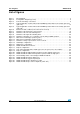
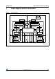
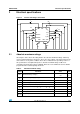
Figure 3. Current and voltage conventions
2.1 Absolute maximum ratings
Stressing the device above the rating listed in the “absolute maximum ratings” table may
cause permanent damage to the device. These are stress ratings only and operation of the
device at these or any other conditions above those indicated in the operating sections of
this specification is not implied. Exposure to absolute maximum rating conditions for
extended periods may affect device reliability. Refer also to the STMicroelectronics SURE
program and other relevant quality document.
V
CC
IN
A
GND
B
I
S
I
OUTA
I
INA
V
INA
V
CC
V
OUTA
I
SENSE
V
OUTB
DIAG
A
/EN
A
I
ENA
I
GND
I
OUTB
IN
B
I
INB
DIAG
B
/EN
B
I
ENB
V
ENB
V
ENA
V
INB
V
SENSE
OUT
A
OUT
B
PWM
CS
I
pw
V
pw
GND
A
GND
CP
V
BAT
I
BAT
V
BAT
V
CP
I
CP
CS_DIS
I
CSD
V
CSD
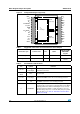
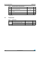
Table 4. Absolute maximum rating
Symbol Parameter Value Unit
V
BAT
Maximum battery voltage
(1)
-16
+41
V
V
V
CC
Maximum bridge supply voltage + 41 V
I
max
Maximum output current (continuous) 30 A
I
R
Reverse output current (continuous) -30 A
I
IN
Input current (IN
A
and IN
B
pins) +/- 10 mA
I
EN
Enable input current (DIAG
A
/EN
A
and DIAG
B
/EN
B
pins) +/- 10 mA
I
pw
PWM input current +/- 10 mA
I
CP
CP output current +/- 10 mA
I
CS_DIS
CS_DIS input current +/- 10 mA