
Data Sheet

Block diagram and pin description VNH5019A-E
6/37 Doc ID 15701 Rev 9
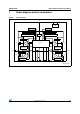
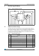
Figure 2. Configuration diagram (top view)
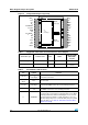
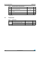
Table 1. Suggested connections for unused and not connected pins
Connection / pin Current sense N.C. OUTx
INPUTx, PWM
DIAGx/ENx
CS_DIS
Floating Not allowed X X X
To ground Through 1 kΩ resistor X Not allowed
Through 10 kΩ
resistor
Table 2. Pin definitions and functions
Pin Symbol Function
1, 25, 30
OUT
A,
Heat Slug2
Source of high-side switch A / drain of low-side switch A, power
connection to the motor
2,14,17, 22,
24,29
N.C. Not connected
3, 13, 23
V
CC
,
Heat Slug1
Drain of high-side switches and connection to the drain of the
external PowerMOS used for the reverse battery protection
12 V
BAT
Battery connection and connection to the source of the external
PowerMOS used for the reverse battery protection
5EN
A
/DIAG
A
Status of high-side and low-side switches A; open drain output.
This pin must be connected to an external pull-up resistor. When
externally pulled low, it disables half-bridge A. In case of fault
detection (thermal shutdown of a high-side FET or excessive
ON-state voltage drop across a low-side FET), this pin is pulled
low by the device (see Table 13: Truth table in fault conditions
(detected on OUTA))
OUT
A
OUT
A
OUT
A
OUT
B
OUT
B
N.C.
V
CC
IN
A
EN
A
/DIAG
A
CS_DIS
PWM
CS
EN
B
/DIAG
B
IN
B
CP
V
BAT
V
CC
OUT
B
N.C.
N.C.
GND
A
GND
A
GND
A
N.C.
V
CC
N.C.
GND
B
GND
B
GND
B
1
15 16
30
V
CC
Heat Slug1
OUT
B
Heat Slug3
OUT
A
Heat Slug2
N.C.