
Data Sheet


List of figures VNH5019A-E
4/37 Doc ID 15701 Rev 9
List of figures
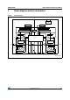
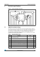
Figure 1. Block diagram . . . . . . . . . . . . . . . . . . . . . . . . . . . . . . . . . . . . . . . . . . . . . . . . . . . . . . . . . . . . 5
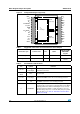
Figure 2. Configuration diagram (top view) . . . . . . . . . . . . . . . . . . . . . . . . . . . . . . . . . . . . . . . . . . . . . 6
Figure 3. Current and voltage conventions . . . . . . . . . . . . . . . . . . . . . . . . . . . . . . . . . . . . . . . . . . . . . 9
Figure 4. Typical application circuit for DC to 20 kHz PWM operation with reverse battery protection
(option A) . . . . . . . . . . . . . . . . . . . . . . . . . . . . . . . . . . . . . . . . . . . . . . . . . . . . . . . . . . . . . . 15
Figure 5. Typical application circuit for DC to 20 kHz PWM operation with reverse battery protection
(option B) . . . . . . . . . . . . . . . . . . . . . . . . . . . . . . . . . . . . . . . . . . . . . . . . . . . . . . . . . . . . . . 16
Figure 6. Behavior in fault condition (how a fault can be cleared) . . . . . . . . . . . . . . . . . . . . . . . . . . . 17
Figure 7. Definition of the delay times measurement . . . . . . . . . . . . . . . . . . . . . . . . . . . . . . . . . . . . 19
Figure 8. Definition of the low-side switching times . . . . . . . . . . . . . . . . . . . . . . . . . . . . . . . . . . . . . . 20
Figure 9. Definition of the high-side switching times . . . . . . . . . . . . . . . . . . . . . . . . . . . . . . . . . . . . . 20
Figure 10. Definition of dynamic cross conduction current during a PWM operation. . . . . . . . . . . . . . 21
Figure 11. Waveforms in full bridge operation (part 1). . . . . . . . . . . . . . . . . . . . . . . . . . . . . . . . . . . . . 22
Figure 12. Waveforms in full bridge operation (part 2). . . . . . . . . . . . . . . . . . . . . . . . . . . . . . . . . . . . . 23
Figure 13. Definition of delay response time of sense current. . . . . . . . . . . . . . . . . . . . . . . . . . . . . . . 24
Figure 14. Half-bridge configuration. . . . . . . . . . . . . . . . . . . . . . . . . . . . . . . . . . . . . . . . . . . . . . . . . . . 24
Figure 15. Multi-motors configuration . . . . . . . . . . . . . . . . . . . . . . . . . . . . . . . . . . . . . . . . . . . . . . . . . 25
Figure 16. MultiPowerSO-30™ PC board . . . . . . . . . . . . . . . . . . . . . . . . . . . . . . . . . . . . . . . . . . . . . . 26
Figure 17. Chipset configuration . . . . . . . . . . . . . . . . . . . . . . . . . . . . . . . . . . . . . . . . . . . . . . . . . . . . . 26
Figure 18. Auto and mutual Rthj-amb vs PCB copper area in open box free air condition . . . . . . . . . 26
Figure 19. Chipset configuration . . . . . . . . . . . . . . . . . . . . . . . . . . . . . . . . . . . . . . . . . . . . . . . . . . . . . 27
Figure 20. MultiPowerSO-30 HSD thermal impedance junction ambient single pulse . . . . . . . . . . . . 28
Figure 21. MultiPowerSO-30 LSD thermal impedance junction ambient single pulse. . . . . . . . . . . . . 28
Figure 22. Thermal fitting model of an H-bridge in MultiPowerSO-30 . . . . . . . . . . . . . . . . . . . . . . . . . 29
Figure 23. MultiPowerSO-30 package dimensions . . . . . . . . . . . . . . . . . . . . . . . . . . . . . . . . . . . . . . . 30
Figure 24. MultiPowerSO-30 suggested pad layout . . . . . . . . . . . . . . . . . . . . . . . . . . . . . . . . . . . . . . 32
Figure 25. MultiPowerSO-30 tube shipment (no suffix) . . . . . . . . . . . . . . . . . . . . . . . . . . . . . . . . . . . 33
Figure 26. MultiPowerSO-30 tape and reel shipment (suffix “TR”) . . . . . . . . . . . . . . . . . . . . . . . . . . . 33