
Data Sheet


Package and PCB thermal data VNH5019A-E
26/37 Doc ID 15701 Rev 9
3 Package and PCB thermal data
3.1 MultiPowerSO-30 thermal data
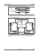
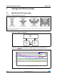
Figure 16. MultiPowerSO-30™ PC board
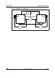
Figure 17. Chipset configuration
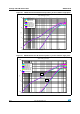
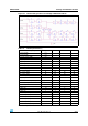
Figure 18. Auto and mutual R
thj-amb
vs PCB copper area in open box free air
condition
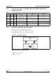
Note:
Layout condition of Rth and Zth measurements (PCB FR4 area= 58 mm x 58 mm, PCB thickness=2 mm, Cu thickness=35 mm, Copper areas:
from minimum pad lay-out to 16 cm
2
).
CHIP 1
R
thA
CHIP 2
CHIP 3
R
thB
R
thC
R
thAB
R
thAC
R
thBC
0
5
10
15
20
25
30
35
40
45
50
0 2 4 6 8 1012141618
cm
2
of Cu Area (refer to PCB layout)
°C/W
RthA
RthB = RthC
RthAB = RthAC
RthBC