
Data Sheet


Electrical specifications VNH5019A-E
24/37 Doc ID 15701 Rev 9
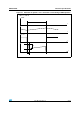
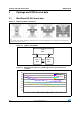
Figure 13. Definition of delay response time of sense current
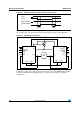
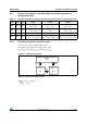
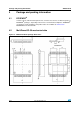
The VNH5019A-E can be used as a high power half-bridge driver achieving an
on- resistance per leg of 9.5 mΩ. The figure below shows the suggested configuration:
Figure 14. Half-bridge configuration
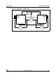
The VNH5019A-E can easily be designed in multi-motors driving applications such as seat
positioning systems where only one motor must be driven at a time. DIAG
X
/EN
X
pins allow
to put unused half-bridges in high-impedance. The figure below shows the suggested
configuration:
CURRENT SENSE
INPUT
LOAD CURRENT
CS_DIS
t
DSENSEH
t
DSENSEL
M
OUT
A
OUT
A
OUT
B
OUT
B
PWM
DIAG
A
/EN
A
IN
A
DIAG
B
/EN
B
IN
B
GND
B
GND
A
GND
B
GND
A
PWM
DIAG
A
/EN
A
IN
A
DIAG
B
/EN
B
IN
B
V
CC
V
CC
CP
CP
V
BAT
V
BAT
CS_DIS
CS_DIS