
Data Sheet


VNH5019A-E Electrical specifications
Doc ID 15701 Rev 9 19/37
2.5 Reverse battery protection
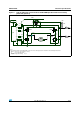
Against reverse battery condition the charge pump feature allows to use an external
N-channel MOSFET connected as shown in the typical application circuit (see
Figure 4
).
As alternative option, a N-channel MOSFET connected to GND pin can be used (see typical
application circuit in figure
Figure 5
).
With this configuration we recommend to short V
BAT
pin to V
CC
.
The device sustains no more than -30 A in reverse battery conditions because of the two
body diodes of the Power MOSFETs. Additionally, in reverse battery condition the I/Os of
VNH5019A-E is pulled-down to the V
CC
line (approximately -1.5 V). Series resistor must be
inserted to limit the current sunk from the microcontroller I/Os. If I
Rmax
is the maximum
target reverse current through microcontroller I/Os, series resistor is:
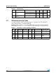
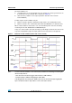
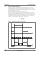
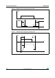
Figure 7. Definition of the delay times measurement
R
V
IOs
V
CC
–
I
Rmax
--------------------------------=
t
t
V
INB
V
INA,
t
PWM
t
I
LOAD
t
DEL
t
DEL