
Data Sheet


Electrical specifications VNH5019A-E
16/37 Doc ID 15701 Rev 9
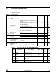
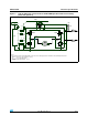
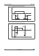
Figure 5. Typical application circuit for DC to 20 kHz PWM operation with reverse battery
protection (option B)
Note: In normal operating conditions the DIAG
X
/EN
X
pin is considered as an input pin by the
device. This pin must be externally pulled high.
In case of a fault condition the DIAG
X
/EN
X
pin is considered as an output pin by the device.
M
μ
C
Reg 5V
+ 5V
HS
A
HS
B
LS
A
LS
B
V
CC
DIAG
A
/EN
A
CS
IN
A
PWM
OUT
A
OUT
B
D
S
G
3.3K
1K
1K
1K
10K
33nF
1.5K
V
CC
100K
V
BAT
CP
DIAG
B
/EN
B
+5V
1K
3.3K
IN
B
1K
GND
A
GND
B
C
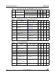
Note:
The value of the blocking capacitor (C) depends on the application conditions and defines voltage and current ripple onto supply line at PWM
operation. Stored energy of the motor inductance may flyback into the blocking capacitor, if the bridge driver goes into 3-state. This causes a
hazardous overvoltage if the capacitor is not big enough. As basic orientation, 500 µF per 10 A load current is recommended.
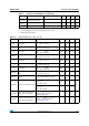
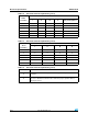
Table 13. Truth table in fault conditions (detected on OUT
A
)
IN
A
IN
B
DIAG
A
/EN
A
DIAG
B
/EN
B
OUT
A
OUT
B
CS
(V
CSD
=0V)
1
1
0
1
OPEN
H
High
impedance
0L
0
1HI
OUTB
/K
0L
High
impedance
X X 0 OPEN
Fault Information Protection Action