
Data Sheet


VNH5019A-E Electrical specifications
Doc ID 15701 Rev 9 15/37
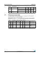
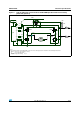
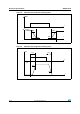
Figure 4. Typical application circuit for DC to 20 kHz PWM operation with reverse battery
protection (option A)
M
μ
C
Reg 5V
+ 5V
HS
A
HS
B
LS
A
LS
B
V
BAT
DIAG
A
/EN
A
CS
IN
A
PWM
OUT
A
OUT
B
3.3K
1K
1K
1K
10K
33nF
1.5K
V
CC
V
BAT
D
S
G
CP
DIAG
B
/EN
B
+5V
1K
3.3K
IN
B
1K
GND
A
GND
B
C
Note:
The external N-channel Power MOSFET used for the reverse battery protection should have the following characteristics:
- BVdss > 20 V (for a reverse battery of -16 V);
- R
DS(on)
< 1/3 of H-bridge total R
DS(on)
- Standard Logic Gate Driving