
Data Sheet

Analog Integrated Circuit Device Data
Freescale Semiconductor 9
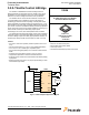
33926
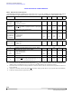
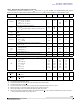
ELECTRICAL CHARACTERISTICS
STATIC ELECTRICAL CHARACTERISTICS
POWER OUTPUTS OUT1, OUT2
R
DS(ON)
Output-ON Resistance, I
LOAD
= 3.0 A
V
PWR
= 8.0 V, T
J
=
25 C
V
PWR
= 8.0 V, T
J
=
150 C
V
PWR
= 5.0 V, T
J
=
150 C
–
–
–
120
–
–
–
225
325
m
(15)
I
LIM
Output Current Regulation Threshold
T
J
< T
FB
T
J
T
FB
(Fold back Region - see Figure 9 and Figure 11)
5.2
–
6.5
4.2
8.0
–
A
(14)
I
SCH
High-side Short-circuit Detection Threshold (Short-circuit to
GND)
11 13 16 A
(14)
I
SCL
Low-side Short-circuit Detection Threshold (Short-circuit to
VPWR)
9.0 11 14 A
(14)
I
OUTLEAK
Output Leakage Current, Outputs off, V
PWR
= 28 V
V
OUT
= V
PWR
V
OUT
= Ground
–
–60
–
–
100
–
A
(16)
V
F
Output MOSFET Body Diode Forward Voltage Drop
I
OUT
= 3.0 A
– – 2.0
V
T
LIM
T
HYS
Overtemperature Shutdown
Thermal Limit at T
J
Hysteresis at T
J
175
–
–
12
200
–
C
(14)
T
FB
Current Foldback at T
J
(14)
165 – 185 C
T
SEP
Current Foldback to Thermal Shutdown Separation
(14)
10 – 15 C
HIGH-SIDE CURRENT SENSE FEEDBACK
I
FB
Feedback Current (pin FB sourcing current)
(17)
I
OUT
= 0 mA
I
OUT
= 300 mA
I
OUT
= 500 mA
I
OUT
= 1.5 A
I
OUT
= 3.0 A
I
OUT
= 6.0 A
0.0
0.0
0.35
2.86
5.71
11.43
–
270
0.775
3.57
7.14
14.29
50
750
1.56
4.28
8.57
17.15
A
A
mA
mA
mA
mA
STATUS FLAG
(18)
I
SFLEAK
Status Flag Leakage Current
V
SF
= 5.0 V
– – 5.0
A
(19)
V
SFLOW
Status Flag SET Voltage
I
SF
= 300 µA
– – 0.4
V
(20)
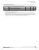
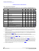
Notes
14. This parameter is guaranteed by design.
15. Output-ON resistance as measured from output to VPWR and from output to GND.
16. Outputs switched OFF via D1 or D2.
17. Accuracy is better than 20% from 0.5 to 6.0 A. Recommended terminating resistor value: R
FB
= 270
18. Status Flag output is an open drain output requiring a pull-up resistor to logic V
DD
.
19. Status Flag Leakage Current is measured with Status Flag HIGH and not SET.
20. Status Flag Set Voltage measured with Status Flag LOW and SET with I
FS
= 300 A. Maximum allowable sink current from this pin is
<
| 500 A | . Maximum allowable pull-up voltage < 7.0 V.
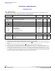
Table 4. Static Electrical Characteristics (continued)
Characteristics noted under conditions 5.0 V V
PWR
28 V, - 40 C T
A
125 C, GND = 0 V, unless otherwise noted. Typical
values noted reflect the approximate parameter means at T
A
= 25 °C under nominal conditions, unless otherwise noted.
Symbol Characteristic Min Typ Max Unit Notes