
Data Sheet

Analog Integrated Circuit Device Data
Freescale Semiconductor 17
33926
FUNCTIONAL DEVICE OPERATION
LOGIC COMMANDS AND REGISTERS
LOGIC COMMANDS AND REGISTERS
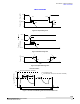
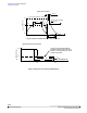
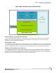
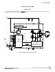
Figure 12. 33926 Power Stage Operation
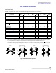
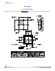
Table 6. Truth Table
The tri-state conditions and the status flag are reset using D1 or D2. The truth table uses the following notations: L = LOW,
H = HIGH, X = HIGH or LOW, and Z = High-impedance. All output power transistors are switched off.
Device State
Input Conditions Status Outputs
EN D1 D2 IN1 IN2 SF OUT1 OUT2
Forward
H L H H L H H L
Reverse
H L H L H H L H
Free Wheeling Low
H L H L L H L L
Free Wheeling High
H L H H H H H H
Disable 1 (D1)
H H X X X L Z Z
Disable 2 (D2)
H X L X X L Z Z
IN1 Disconnected
H L H Z X H H X
IN2 Disconnected
H L H X Z H X H
D1 Disconnected
H Z X X X L Z Z
D2 Disconnected
H X Z X X L Z Z
Undervoltage Lockout
(30)
H X X X X L Z Z
Overtemperature
(31)
H X X X X L Z Z
Short-circuit
(31)
H X X X X L Z Z
Sleep Mode EN
L X X X X H Z Z
EN Disconnected
Z X X X X H Z Z
Notes
30. In the event of an undervoltage condition, the outputs tri-state and status flag is SET logic LOW. Upon undervoltage recovery, status
flag is reset automatically or automatically cleared and the outputs are restored to their original operating condition.
31. When a short-circuit or overtemperature condition is detected, the power outputs are tri-state latched-OFF, independent of the input
signals, and the status flag is latched to logic LOW. To reset from this condition requires the toggling of either D1,
D2, EN, or V
PWR
.
OUT1 OUT2
PGND
V
PWR
V
PWR
PGND
LOAD
Load
Current
Forward
OFF
ON
ON
OFF
OUT1 OUT2
PGND
OFF
ON
ON
OFF
V
PWR
V
PWR
PGND
LOAD
Load
Current
Reverse
OUT1 OUT2
PGND
V
PWR
V
PWR
PGND
LOAD
Load
Current
High-Side Recirculation
(Forward)
ON
OFF
ON
OFF
OUT1 OUT2
PGND
V
PWR
V
PWR
PGND
LOAD
Load
Current
Low-Side Recirculation
(Forward)
ON ON
OFF OFF