
Manual
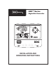


INSTALLATION INSTRUCTIONS: OUTDOOR MODELS
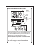
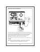
Remove the lower cover of the DDC controller by sliding it down. Place the unit on
the wall using the top keyhole screw slot. Level the controller, then insert screws
into one or more of the three lower screws holes at of the cabinet bottom. Drive
the screws through the plastic flashing that keeps the cabinet weather resistant. If
installing the controller on drywall or masonry, install screw anchors to prevent the
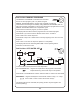
screws from loosening. Connect the solenoid wires to the terminal block through
the 12mm (
1
/2”) hole in the right side of the cabinet bottom. If the solenoid wires
are being installed in conduit, there is a knock-out on this hole that will accept a
24mm (1”) male conduit adapter. Connect the wires as shown for the indoor
model. Last, connect the power wires.
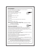
Warning: AC power wiring must be installed and connected by
qualified personnel only. All electrical components and installation
procedures must comply with all local and national electrical codes. Some
codes may require a means of disconnection from the AC power source
installed in the fixed wiring and having a contact separation of at least 3mm
(0.120”) in the line and neutral poles. Make sure the power is OFF prior to
connecting the controller.
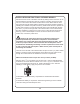
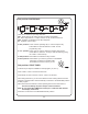
The hole on the left side of the cabinet bottom accepts a 12mm (
1
/2”) male conduit
adapter. Route the power and equipment ground wires from the power source,
through the conduit and into the transformer connector compartment.
NOTE: The terminal block accepts wire size up to 4mm (12 AWG).
Remove 10mm (
3
/8”) of insulation from the wire ends. Using a small flat bladed
screwdriver, secure the wires as follows: Line or Line 1 (L1) to L, Neutral or Line 2
(L2) to N and Equipment Ground to G. Install compartment cover. After first
installing a 9 VDC battery, apply AC power to the controller.
9 VDC battery. The 9 volt battery compartment is located below the 24VAC
terminals.
A standard 9V battery is required for Armchair Programming
TM
and to maintain
clock time during an extended power loss.
-4-