
User Manual

點晶科技股份有限公司
SILICON TOUCH TECHNOLOGY INC. DM163
8x3-CHANNEL CONSTANT CURRENT LED DRIVERS Version: A.004 Page 14
Particular Phenomenon
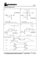
DM163 incorporates a different PWM counter, as described in Figure 2, hence its output
waveform demonstrate a very different characteristics compare to conventional PWM counter.
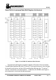
(1) Nonconsecutive counter
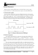
The non-consecutive PWM counter incorporate by DM163 demonstrated a waveform pattern
similar to Figure 7. Its waveform is spread-out into each PWM cycle, resulting lots of intermediate
pulses during each PWM cycle. In Fig 7, if all the intermediate pulses are added up, it would
equal to 50% luminance which is the same as the conventional method. By spreading out the
PWM pulses, this approach can help prevent LED from flickering in lower grayscale situation.
Figure 7. An Example of Nonconsecutive PWM Signal
(2) 8+6 bits Comparator
The comparator illustrated in Fig 2 is another one of the unique designs in DM163. The
comparator’s output will be “H” only when value at “+” is larger then the value at “-“ (in other
word, comparator will be “L” when value in“+” equals to value in “-“ or value in “+” is less than
value in “-“). Only when both 8 bit and 6 bit comparator are “H” will there be current in the output
channel.
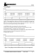
Due to this unique comparator design, DM163 exhibit a very distinct output characters in
two certain scenario. In the first case, DM163 output will always be “OFF” when either one of the 8
bit or 6 bit bank is filled with 0. In 2
nd
scenario, when all bit value at both 8 bit and 6 bit bank are
loaded “H”, DM163 output will exhibit its highest luminance value (but not 100% luminance value).
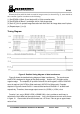
Due to the nature of comparators design, PWM control signal will be zero in the condition of 8bits
counter=8’bFF or 6bits counter=6’b3F. Consequently, the PWM control signal will be 0 for
2
8
+2
6
+1 GCK rather than always high.